Advertisement
Quick Links
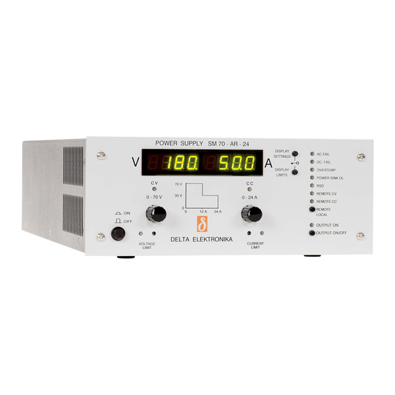
DELTA ELEKTRONIKA B.V.
DC POWER SUPPLIES
SM800-series
SM7.5-80
SM18-50
SM70-AR-24
SM400-AR-4
Product Manuals and Driver & Example Software
For several Applications, build-in Options and Interfaces there are Application
Notes, separate Product Manuals and Driver & Example Software available on
our website. See PRODUCTS\SM800\DOWNLOADS.
PRODUCT MANUAL
Contents:
–
1
Safety Instructions
–
2
Sicherheitshinweise
–
3
General
–
4
Installation
–
5
Trouble Shooting
–
6
Maintenance & Calibration
–
7
EU Declaration of Conformity
–
8
UK Declaration of Conformity
1 / 22
Vissersdijk 4, 4301 ND
Zierikzee, the Netherlands
DELTA ELEKTRONIKA B.V.
www.DeltaPowerSupplies.com
Tel. +31 111 413656
rev. Jan. 2021
Advertisement

Related Manuals for Delta Elektronika SM800 Series


Summary of Contents for Delta Elektronika SM800 Series
- Page 1 DELTA ELEKTRONIKA B.V. Vissersdijk 4, 4301 ND www.DeltaPowerSupplies.com DC POWER SUPPLIES Zierikzee, the Netherlands Tel. +31 111 413656 SM800-series SM7.5-80 SM18-50 SM70-AR-24 SM400-AR-4 Product Manuals and Driver & Example Software For several Applications, build-in Options and Interfaces there are Application Notes, separate Product Manuals and Driver &...
- Page 2 Failure to comply with the safety precautions or warnings in this document violates safety standards of design, manufacture and intended use of this equipment and may impair the built-in protections. Delta Elektronika shall not be liable for user’s failure to comply with these requirements.
- Page 3 Warning! High currents can run through the DC power terminals. These currents cause strong magnetic fields. Do not come near if you have an electro medical device such as a pacemaker. 1.15 Environmental Conditions The Delta Elektronika power supplies safety approval applies to the following operating conditions: Usage : Indoor use only.
- Page 4 Die Nichteinhaltung der Sicherheitsvorkehrungen oder Warnungen in diesem Dokument verstößt gegen die Sicherheitsstandards im Hinblick auf Bauart, Produktion und vorgesehene Nutzung dieses Geräts und kann die eingebauten Schutzvorrichtungen beschädigen. Delta Elektronika haftet nicht dafür, wenn der Nutzer diesen Anforderungen nicht nachkommt.
- Page 5 SM800 2.10 Teileaustausch & Modifikationen Teileaustausch und Modifikationen sind ausschließlich autorisiertem Delta Elektronika-Service-Personal gestattet. Reparaturen am Gerät dürfen nur durch eine Delta Elektronika-Serviceeinrichtung durchgeführt werden. 2.11 Entfernung von (Sicherheits-) Abdeckungen Sicherheitsabdeckung(en) werden verwendet, um potenziell gefährliche Spannungen abzudecken. Beachten Sie Folgendes, wenn Sie die Sicherheitsabdeckung(en) entfernen: ...
- Page 6 When the unit is in CC-mode most of the time, it is fig 3 - 3 possible to disable the LED with DIP switch 3 on SW1 (rear panel). Measuring ripple voltage RIGHT! 6 / 22 DELTA ELEKTRONIKA B.V. rev. Jan. 2021...
- Page 7 With the ISO AMP CARD earth loops between the unit and the programming source are prevented. 3.11 ETH / IEEE488 / RS232 PROGRAMMING The Delta Elektronika PSC-ETH, PSC-488 and PSC-232 controllers can be factory installed inside the unit. Voltage and current can easily be programmed and read back.
- Page 8 A. Once the unit is switched on, the voltage and current can be set to the preferred value. * = SW1-5 only on units with optional digital encoders (option P236). 8 / 22 DELTA ELEKTRONIKA B.V. rev. Jan. 2021...
- Page 9 For safety the insulation of the separating components fig 3 - 15 (transformers) between mains in and DC output is tested at Insulation test voltages. 3750 Vrms during 1 minute. This is tested before assembly. 9 / 22 DELTA ELEKTRONIKA B.V. rev. Jan. 2021...
- Page 10 CON E are connected to the sense leads and Remote sensing, voltage drop in load leads subtracts therefore read the voltage across the load and not the voltage from maximum output. on the DC output terminals. 10 / 22 DELTA ELEKTRONIKA B.V. rev. Jan. 2021...
- Page 11 PSC-488 or the PSC-232. Slave unit: Connect CON C to Master. Connect CON B to Slave2. Warning: Never connect CON C to CON C! See next chapter for more details. 11 / 22 DELTA ELEKTRONIKA B.V. rev. Jan. 2021...
- Page 12 For long life the temperature of the air entering at the rear should be below 35 °C under normal conditions. Under extreme conditions it should be below 50 °C. 3.35 DIMENSIONS fig 3 – 25 Unit dimensions. 12 / 22 DELTA ELEKTRONIKA B.V. rev. Jan. 2021...
- Page 13 Low resistive cable connection by mounting the By pressing the DISPLAY CV/CC SETTING button the meters cables directly on the DC output strips. will show the setting of the CV and CC potentiometer. 13 / 22 DELTA ELEKTRONIKA B.V. rev. Jan. 2021...
- Page 14 4 - 5 series (F27_1 on P650). To avoid earth loops, use an isolated Local sensing. programming source. If this is not possible, see next paragraph for using the optional ISO AMP CARD. 14 / 22 DELTA ELEKTRONIKA B.V. rev. Jan. 2021...
- Page 15 Once the output is set at the correct voltage the battery will charge constantly without overcharging. This can fig 4 - 8 be useful for emergency power systems. Charging a battery with a circuit breaker in series. 15 / 22 DELTA ELEKTRONIKA B.V. rev. Jan. 2021...
- Page 16 If the RJ45 connector is removed from CON C when the unit fig 4 - 11 is turned on, the output will shutdown to avoid accidental Master / Slave parallel connections. damage. 16 / 22 DELTA ELEKTRONIKA B.V. rev. Jan. 2021...
- Page 17 CC-mode. The parallel slave must be in Remote CC-mode and the CV-potmeter must be fully opened. Note: A Master / Slave combination can always be programmed, also with the IEEE488/RS232 controller (PSC- 488 / PSC-232). 17 / 22 DELTA ELEKTRONIKA B.V. rev. Jan. 2021...
- Page 18 5 - 1. To check the fuse measure the voltage between Ø and the minus output, a high voltage means too much current flowing through the fuse. F27_2 = 650 mA, self resetting. 18 / 22 DELTA ELEKTRONIKA B.V. rev. Jan. 2021...
- Page 19 Do not try to repair, but send for repair. See paragraph 1). 5.15 Other If the problem persists, please fill out the RMA-form on our website www.DeltaPowerSupplies.com. See previous paragraph 1). 19 / 22 DELTA ELEKTRONIKA B.V. rev. Jan. 2021...
- Page 20 CC mode. Calibrate the current with R26_41 exactly on the rated max. current. Warning! Wrong calibration can damage the unit. fig 6 -3 Calibrating maximum current and offset on P650. 20 / 22 DELTA ELEKTRONIKA B.V. rev. Jan. 2021...
- Page 21 CE DECLARATION SM800 DELTA ELEKTRONIKA B.V. Vissersdijk 4, 4301 ND www.DeltaPowerSupplies.com DC POWER SUPPLIES Zierikzee, the Netherlands Tel. +31 111 413656 EU Declaration of Conformity – SM800-series Delta Elektronika Vissersdijk 4 4301 ND ZIERIKZEE The Netherlands Declare under sole responsibility that the following Power Supplies: SM 7.5-80...
- Page 22 UK DECLARATION SM800 DELTA ELEKTRONIKA B.V. Vissersdijk 4, 4301 ND www.DeltaPowerSupplies.com DC POWER SUPPLIES Zierikzee, the Netherlands Tel. +31 111 413656 UK Declaration of Conformity – SM800-series Product: SM800 Power Supply Series Model Numbers: SM 7.5-80, SM 18-50, SM 70-AR-24, SM 400-AR-4.
Need help?
Do you have a question about the SM800 Series and is the answer not in the manual?
Questions and answers