Table of Contents
Advertisement
Quick Links
Advertisement
Table of Contents

Related Manuals for Baumer Hubner HOG 10 + DSL


Summary of Contents for Baumer Hubner HOG 10 + DSL
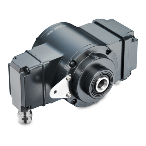
- Page 1 Montage- und Betriebsanleitung Mounting and operating instructions HOG 10 + DSL Kombination Inkrementaler Drehgeber mit integriertem programmierbaren, digitalen Drehzahlschalter Combination Incremental encoder with integrated programmable, digital speed switch...
-
Page 2: Table Of Contents
Inhaltsverzeichnis Inhaltsverzeichnis Allgemeine Hinweise ................................Betrieb in explosionsgefährdeten Bereichen ....................Sicherheitshinweise ................................Vorbereitung .................................... Lieferumfang ................................Zur Montage erforderlich (nicht im Lieferumfang enthalten) ............. Zur Demontage erforderlich (nicht im Lieferumfang enthalten) ............. Erforderliches Werkzeug (nicht im Lieferumfang enthalten) ............Montage ..................................... - Page 3 Table of contents Table of contents General notes ..................................Operation in potentially explosive environments ................... Security indications ................................Preparation ....................................Scope of delivery ..............................Required for mounting (not included in scope of delivery) ..............Required for dismounting (not included in scope of delivery) ............
-
Page 4: Allgemeine Hinweise
Gebrauchte Elektro- und Elektronikgeräte dürfen nicht im Hausmüll entsorgt werden. Das Produkt enthält wertvolle Rohstoffe, die recycelt werden können. Wenn immer möglich sollen Altgeräte lokal am entsprechenden Sammeldepot entsorgt werden. Im Bedarfsfall gibt Baumer den Kunden die Möglichkeit, Baumer-Produkte fachgerecht zu entsor- gen. Weitere Informationen siehe www.baumer.com. Achtung! Beschädigung des auf dem Gerät befindlichen Siegels... -
Page 5: General Notes
Whenever possible, waste electrical and electronic equipment should be disposed locally at the authorized collection point. If necessary, Baumer gives customers the opportunity to dispose of Baumer products profession- ally. For further information see www.baumer.com. -
Page 6: Betrieb In Explosionsgefährdeten Bereichen
Betrieb in explosionsgefährdeten Bereichen Betrieb in explosionsgefährdeten Bereichen Das Gerät entspricht der Richtlinie 2014/34/EU für explosionsgefährdete Bereiche. Der Einsatz ist gemäß den Gerätekategorien 3 G (Ex-Atmosphäre Gas) und 3 D (Ex-Atmo- sphäre Staub) zulässig. Das Relaismodul DS 93 R (als Zubehör erhältlich, siehe Abschnitt 7.2.5) darf nicht in explosions- gefährdeten Bereichen eingesetzt werden. -
Page 7: Operation In Potentially Explosive Environments
Operation in potentially explosive environments Operation in potentially explosive environments The device complies with the directive 2014/34/EU for potentionally explosive atmospheres. It can be used in accordance with equipment categories 3 G (explosive gas atmosphere) and 3 D (explosive dust atmosphere). The relais module DS 93 R (available as accessory, see section 7.2.5) must not be used in potentionally explosive atmospheres. -
Page 8: Sicherheitshinweise
Sicherheitshinweise Sicherheitshinweise Verletzungsgefahr durch rotierende Wellen Haare und Kleidungsstücke können von rotierenden Wellen erfasst werden. • Vor allen Arbeiten alle Betriebsspannungen ausschalten und Maschinen stillsetzen. Zerstörungsgefahr durch elektrostatische Aufladung Die elektronischen Bauteile im Gerät sind empfindlich gegen hohe Spannungen. • Steckkontakte und elektronische Komponenten nicht berühren. •... -
Page 9: Security Indications
Security indications Security indications Risk of injury due to rotating shafts Hair and clothes may become tangled in rotating shafts. • Before all work switch off all voltage supplies and ensure machinery is stationary. Risk of destruction due to electrostatic charge Electronic parts contained in the device are sensitive to high voltages. -
Page 10: Vorbereitung
Vorbereitung / Preparation Vorbereitung Preparation Lieferumfang Scope of delivery Gehäuse Housing Stützblech für Drehmomentstütze Support plate for torque arm Sechskantschraube M6x18 mm, ISO 4017 Hexagon screw M6x18 mm, ISO 4017 Scheibe B6,4, ISO 7090 Washer B6.4, ISO 7090 Selbstsichernde Mutter M6, ISO 10511 Self-locking nut M6, ISO 10511 Spannelement Clamping element... - Page 11 Vorbereitung / Preparation Lieferumfang Scope of delivery Einseitig offene Hohlwelle mit Schlüsselfläche Blind hollow shaft with spanner flat SW 17 17 a/f Abdeckung mit O-Ring Cover with o-ring Ejot-Innensechskantschraube M4x14 mm Ejot hexagon socket screw M4x14 mm Klemmenkastendeckel HOG 10 Terminal box cover HOG 10 Torx-/Schlitzschraube M4x32 mm Torx/slotted screw M4x32 mm Kabelverschraubung M20x1,5 mm Cable gland M20x1.5 mm...
-
Page 12: Zur Montage Erforderlich (Nicht Im Lieferumfang Enthalten)
Vorbereitung / Preparation Zur Montage erforderlich Required for mounting (nicht im Lieferumfang enthalten) (not included in scope of delivery) 25b 25c Drehmomentstütze, als Zubehör erhältlich: Torque arm, available as accessory: Bestellnummer Länge L, Version Order number Length L, version 11043628 67...70 mm, Standard 11043628 67...70 mm, standard 11004078... -
Page 13: Zur Demontage Erforderlich (Nicht Im Lieferumfang Enthalten)
Vorbereitung / Preparation Zur Demontage erforderlich Required for dismounting (nicht im Lieferumfang enthalten) (not included in scope of delivery) Montage-/Demontageset als Zubehör erhält- Mounting/dismounting kit available as acces- lich: sory: Bestellnummer 11077087, bestehend aus ... Order number 11077087, including ... Gewindestift M6x10 mm, ISO 7436 Setscrew M6x10 mm, ISO 7436 Zylinderschraube M8x45 mm, ISO 4762 Cylinder screw M8x45 mm, ISO 4762 Erforderliches Werkzeug... -
Page 14: Montage
Montage / Mounting Montage Mounting Schritt 1 Step 1 10 mm 10 mm Schritt 2 Step 2 3 mm * Siehe Seite 7, 8 oder 9 See page 7, 8 or 9 MB143T1 - 11070464 Baumer_HOG10-DSL-T1_II_DE-EN (19A1) -
Page 15: Schritt 3
Montage / Mounting Schritt 3 Step 3 Zentrierbohrung Center hole DIN 332-D, M6x16 mm 53 mm 52 mm (40...52 mm) 16 mm * Siehe Seite 7 oder 8 See page 7 or 8 Antriebswelle einfetten. Lubricate drive shaft. Die Antriebswelle sollte einen The drive shaft should have as less möglichst kleinen Rundlauffehler runout as possible because this can... - Page 16 Montage / Mounting Schritt 4 Step 4 Zul. Anzugsmoment: 17 mm Max. tightening torque: = 6 Nm 5 mm 10 mm 1.6x8 mm * Siehe Seite 9 See page 9 MB143T1 - 11070464 Baumer_HOG10-DSL-T1_II_DE-EN (19A1)
-
Page 17: Schritt 5 - Drehmomentstütze
Montage / Mounting Schritt 5 - Drehmomentstütze Step 5 - Torque arm Die Montage der Drehmomentstütze The torque arm should be mounted sollte spielfrei erfolgen. Ein Spiel von free from clearance. A play of just beispielsweise ±0,03 mm entspricht ±0.03 mm, results in a runout of the einem Rundlauffehler des Gerätes von combination of 0.06 mm. -
Page 18: Hinweis Zur Vermeidung Von Messfehlern
Montage / Mounting Hinweis zur Vermeidung von Messfeh- How to prevent measurement errors lern Für einen einwandfreien Betrieb des To ensure that the device operates cor- Gerätes ist eine korrekte Montage, ins- rectly, it is necessary to mount it accu- besondere auch der Drehmomentstütze, rately as described in section 5.1 to 5.5, notwendig, wie beschrieben in Abschnitt... -
Page 19: Schritt 6
Montage / Mounting Schritt 6 Step 6 3 mm Zul. Anzugsmoment Max. tightening torque = 2...3 Nm * Siehe Seite 8 See page 8 Montagehinweis Mounting instruction Wir empfehlen, das Gerät so zu It is recommended to mount the device montieren, dass der Kabelanschluss with cable connection facing down- keinem direkten Wassereintritt... -
Page 20: Abmessung
Abmessung / Dimension Abmessung Dimension (74069, 74650, 74661) (74069, 74650, 74661) Um 90° versetzt gezeichnet Drawing 90° rotated Zubehör Accessory Positive Drehrichtung Positive rotating direction Alle Abmessungen in Millimeter (wenn nicht anders angegeben) All dimensions in millimeters (unless otherwise stated) MB143T1 - 11070464 Baumer_HOG10-DSL-T1_II_DE-EN (19A1) -
Page 21: Elektrischer Anschluss
Elektrischer Anschluss / Electrical connection Elektrischer Anschluss Electrical connection HOG 10 HOG 10 7.1.1 Beschreibung der Anschlüsse 7.1.1 Terminal significance Betriebsspannung +UB; + Voltage supply Masseanschluss ; ; GND; 0V Ground Erdungsanschluss (Gehäuse) Earth ground (housing) Ausgangssignal Kanal 1 K1; A; A+ Output signal channel 1 Ausgangssignal Kanal 1 invertiert K1;... -
Page 22: Kabelanschluss
Elektrischer Anschluss / Electrical connection HOG 10 HOG 10 7.1.3 Kabelanschluss 7.1.3 Cable connection 7.1.3.1 Schritt 1 7.1.3.1 Step 1 TX 20 18 * 22 mm 7.1.3.2 Schritt 2 7.1.3.2 Step 2 TX 10 * Siehe Seite 8 See page 8 MB143T1 - 11070464 Baumer_HOG10-DSL-T1_II_DE-EN (19A1) - Page 23 Elektrischer Anschluss / Electrical connection 7.1.3.3 Schritt 3 und 4 7.1.3.3 Step 3 und 4 19 * Ansicht X siehe Abschnitt 7.1.4. Kabelschirm View X Cable shield 18 * see section 7.1.4. ø5...13 mm Zur Gewährleistung der angegebenen To ensure the specified protection of Schutzart sind nur geeignete Kabel- the device the correct cable diameter durchmesser zu verwenden.
- Page 24 Elektrischer Anschluss / Electrical connection HOG 10 HOG 10 7.1.3 Kabelanschluss 7.1.3 Cable connection 7.1.3.5 Schritt 6 7.1.3.5 Step 6 Zul. Anzugsmoment Max. tightening torque = 2...3 Nm TX 20 Großer, um 180° wendbarer Klemmenkasten. Big terminal box, turn by 180°. * Siehe Seite 8 See page 8 Vor der Montage des Klemmenkasten- Check that the seal of the terminal box...
-
Page 25: Klemmenbelegung
Sensorkabel HEK 8 (Zubehör) 7.1.5 Sensor cable HEK 8 (accessory) Es wird empfohlen, das Baumer Hübner Baumer Hübner sensor cable HEK 8 is Sensorkabel HEK 8 zu verwenden oder recommended. As a substitute a shielded ersatzweise ein geschirmtes, paarig ver- twisted pair cable should be used. -
Page 26: Dsl.r Für Den Betrieb Mit Einem Externen Relaismodul Ds 93 R (Zubehör)
Elektrischer Anschluss / Electrical connection DSL.R für den Betrieb mit einem exter- DSL.R suitable for operation with the nen Relaismodul DS 93 R (Zubehör) external relay modul DS 93 R (acces- sory) 7.2.1 Kabelanschluss 7.2.1 Cable connection 7.2.1.1 Schritt 1 7.2.1.1 Step 1 TX 20 11 * 22 mm... - Page 27 Elektrischer Anschluss / Electrical connection 7.2.1.2 Schritt 2 7.2.1.2 Step 2 Kabelschirm Cable shield Zul. Anzugsmoment Max. tightening torque = 2...3 Nm TX 20 Ansicht Y 11 * siehe Abschnitt 7.2.2. View Y see section 7.2.2. 22 mm ø5...13 mm Um 180° wendbarer Klemmenkasten. Terminal box, turn by 180°.
-
Page 28: Klemmenbelegung
RS485 Schnittstelle für PC oder Laptop (Adapter erforderlich). Interface for PC or Laptop (adapter required). Programmierung des DSL über Software zum Download unter www.baumer.com: Software für Windows XP Benutzerhandbuch für Windows XP Software für Windows 7-10 Benutzerhandbuch für Windows 7-10 Programming of the DSL via software available for download at www.baumer.com:... -
Page 29: Blockschaltbild
Elektrischer Anschluss / Electrical connection 7.2.3 Blockschaltbild 7.2.3 Block diagramm Kombination/Combination 15...30 VDC High = 12 V, Low = 0 V HOG 10 DSL.R 0 V (GND) RS485 für/for PC/Laptop A, B 0 V (GND) 7.2.4 Ausgangsschaltverhalten 7.2.4 Switching characteristics 12 VDC 1,2,3 0 V (GND) -ns off -ns on... -
Page 30: Ds 93 R Relaismodul (Zubehör)
Elektrischer Anschluss / Electrical connection 7.2.5 DS 93 R Relaismodul (Zubehör) 7.2.5 DS 93 R relay modul (accessory) 7.2.5.1 Klemmenbelegung 7.2.5.1 Terminal assignment 3 Kontroll-LED‘s Höhe = 55 mm 3 control LEDs Kunststoffgehäuse für Tragschienenmontage (EN 50022) IP 20 Height = 55 mm 3 Relais/relays Plastic housing for ≤6 A / 250 VAC... -
Page 31: Dsl.e Mit Drei Internen Elektronischen Relais
Elektrischer Anschluss / Electrical connection DSL.E mit drei internen elektronischen DSL.E with three internal electronic Relais relays 7.3.1 Kabelanschluss 7.3.1 Cable connection 7.3.1.1 Schritt 1 7.3.1.1 Step 1 TX 20 11 * 22 mm * Siehe Seite 7 See page 7 MB143T1 - 11070464 Baumer_HOG10-DSL-T1_II_DE-EN (19A1) - Page 32 Elektrischer Anschluss / Electrical connection 7.3.1.2 Schritt 2 7.3.1.2 Step 2 Kabelschirm Cable shield Zul. Anzugsmoment Max. tightening torque = 2...3 Nm TX 20 Ansicht Z 11 * siehe Abschnitt 7.3.2. View Z see section 7.3.2. 22 mm ø5...13 mm Um 180° wendbarer Klemmenkasten. Terminal box, turn by 180°.
-
Page 33: Klemmenbelegung
Control output RS485 Schnittstelle für PC oder Laptop (Adapter erforderlich). Interface for PC or Laptop (adapter required). Programmierung des DSL über Software zum Download unter www.baumer.com: Software für Windows XP Benutzerhandbuch für Windows XP Ansicht Z Software für Windows 7-10 siehe Abschnitt 7.3.1.2. -
Page 34: Blockschaltbild
Elektrischer Anschluss / Electrical connection 7.3.3 Blockschaltbild 7.3.3 Block diagramm Kombination/Combination C1-A I>5 mA C1-B 9...30 VDC R1-A I>5 mA R1-B HOG 10 DSL.E R2-A I>5 mA R2-B RS 485 A, B für/for PC/Laptop 0 V (GND) MB143T1 - 11070464 Baumer_HOG10-DSL-T1_II_DE-EN (19A1) -
Page 35: Demontage
Demontage / Dismounting Demontage Dismounting Schritt 1 Step 1 TX 10 17 * TX 20 18 * 22 mm TX 20 11 * 22 mm * Siehe Seite 7, 8 oder 9 See page 7, 8 or 9 MB143T1 - 11070464 Baumer_HOG10-DSL-T1_II_DE-EN (19A1) - Page 36 Demontage / Dismounting Schritt 2 Step 2 TX 10 20 * TX 20 18 * 22 mm TX 20 11 * 22 mm * Siehe Seite 7 oder 8 See page 7 or 8 MB143T1 - 11070464 Baumer_HOG10-DSL-T1_II_DE-EN (19A1)
- Page 37 Demontage / Dismounting Schritt 3 Step 3 10 mm 1.6x8 mm Schritt 4 Step 4 3 mm * Siehe Seite 7, 8 oder 9 See page 7, 8 or 9 MB143T1 - 11070464 Baumer_HOG10-DSL-T1_II_DE-EN (19A1)
- Page 38 Demontage / Dismounting Schritt 5 Step 5 17 mm 5 mm Schritt 6 Step 6 0.8x4 mm * Siehe Seite 9 oder 10 See page 9 or 10 MB143T1 - 11070464 Baumer_HOG10-DSL-T1_II_DE-EN (19A1)
- Page 39 Demontage / Dismounting Schritt 7 Step 7 17 mm 6 mm Schritt 8 Step 8 * Siehe Seite 10 See page 10 MB143T1 - 11070464 Baumer_HOG10-DSL-T1_II_DE-EN (19A1)
-
Page 40: Technische Daten
Technische Daten Technische Daten Technische Daten - elektrisch • Betriebsstrom ohne Last: ≤200 mA HOG 10 + DSL.E • Betriebsspannung: 9...30 VDC HOG 10 + DSL.R • Betriebsspannung: 15...30 VDC Technische Daten - elektrisch (Drehgeber) • Impulse pro Umdrehung: 512...2500 (je nach Bestellung) •... -
Page 41: Technische Daten - Mechanisch
Technische Daten - mechanisch • Baugröße (Flansch): ø105 mm • Wellenart: ø16 mm (einseitig offene Hohlwelle) • Zulässige Wellenbelastung: ≤450 N axial ≤600 N radial • Schutzart DIN EN 60529: IP66 • Drehzahl (n): ≤6000 U/min (mechanisch) • Schaltdrehzahlbereich (ns): Impulszahl = 512: ±16...6000 U/min Impulszahl = 1024: ±8...6000 U/min... -
Page 42: Technical Data
Technical data Technical data Technical data - electrical ratings • Consumption w/o load: ≤200 mA HOG 10 + DSL.E • Voltage supply: 9...30 VDC HOG 10 + DSL.R • Voltage supply: 15...30 VDC Technical data - electrical ratings (encoder) • Pulses per revolution: 512...2500 (as ordered) •... -
Page 43: Technical Data - Mechanical Design
Technical data - mechanical design • Size (flange): ø105 mm • Shaft type: ø16 mm (blind hollow shaft) • Admitted shaft load: ≤450 N axial ≤600 N radial • Protection DIN EN 60529: IP66 • Speed (n): ≤6000 rpm • Range of switching speed (ns ): Pulses = 512: ±16...6000 rpm Pulses = 1024: ±8...6000 rpm Pulses = 2048:... -
Page 44: Zubehör
3 x Umschalter 3 x change-over switch (≤6 A/250 VAC, ≤1 A/48 VDC) (≤6 A/250 VAC, ≤1 A/48 VDC) • Software zum Download unter • Software for download at www.baumer.com www.baumer.com • DSL-Benutzerhandbuch zum • DSL user manual for download at Download unter www.baumer.com www.baumer.com 10.3... -
Page 45: Eu-Konformitätserklärung
Signature/nom/fonction Baumer_POGxDSL_HOGxDSL_DE-EN-FR_CoC_81201223.docm/kwe Baumer Hübner GmbH P.O. Box 126943 ∙ D-10609 Berlin ∙ Max-Dohrn-Str. 2+4 ∙ D-10589 Berlin Phone +49 (0)30 69003-0 ∙ Fax +49 (0)30 69003-104 ∙ info@baumerhuebner.com ∙ www.baumer.com Sitz der Gesellschaft / Registered Office: Berlin, Germany ∙ Geschäftsführer / Managing Director: Dr. Oliver Vietze, Dr. Johann Pohany Handelsregister / Commercial Registry: AG Charlottenburg HRB 96409 ∙... - Page 46 MB143T1 - 11070464 Baumer_HOG10-DSL-T1_II_DE-EN (19A1)
- Page 47 MB143T1 - 11070464 Baumer_HOG10-DSL-T1_II_DE-EN (19A1)
- Page 48 Baumer Hübner GmbH P.O. Box 12 69 43 · 10609 Berlin, Germany Phone: +49 (0)30/69003-0 · Fax: +49 (0)30/69003-104 info@baumerhuebner.com · www.baumer.com/motion Version: 74069, 74650, 74661 MB143T1 - 11070464 Baumer_HOG10-DSL-T1_II_DE-EN (19A1-25.02.2019)
Need help?
Do you have a question about the Hubner HOG 10 + DSL and is the answer not in the manual?
Questions and answers