Baumer Hübner HOG 10 G Installation And Operating Instructions Manual
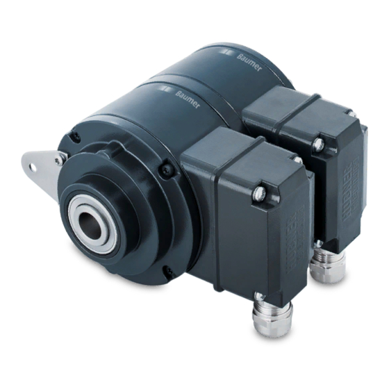
Incremental encoder, twin encoder
Hide thumbs
Also See for Hübner HOG 10 G:
- Installation and operating instructions manual (36 pages) ,
- Mounting and operating instructions (40 pages) ,
- Mounting and operating instructions (36 pages)

Related Manuals for Baumer Hübner HOG 10 G


Summary of Contents for Baumer Hübner HOG 10 G
- Page 1 Montage- und Betriebsanleitung Installation and operating instructions HOG 10 G Zwillingsgeber Twin Encoder HOG 10 Drehimpulsgeber Incremental Encoder...
-
Page 2: Table Of Contents
Inhaltsverzeichnis Inhaltsverzeichnis Allgemeine Hinweise ..............................Betrieb in explosionsgefährdeten Bereichen ..................... Sicherheitshinweise ..............................Vorbereitung ..................................4.1 Lieferumfang ................................ 4.2 zur Montage erforderlich bzw. empfohlen (nicht im Lieferumfang enthalten) ......4.3 zur Demontage erforderlich (nicht im Lieferumfang enthalten) ............ Montage ....................................5.1 Schritt 1 ................................... 5.2 Schritt 2 ... - Page 3 Table of contents Table of contents General notes ................................... Operation in potentially explosive environments ..................Security indications ..............................Preparation ..................................4.1 Scope of delivery ............................... 4.2 required resp. recommended for mounting (not included in scope of delivery) ....... 4.3 required for dismounting (not included in scope of delivery) ............Mounting ....................................5.1 Step 1 ..................................5.2 Step 2 ...
-
Page 4: Allgemeine Hinweise
Allgemeine Hinweise Allgemeine Hinweise 1.1 Der Drehimpulsgeber HOG 10 (Zwillingsgeber HOG 10 G) ist ein opto-elektronisches Präzi- sionsmessgerät, das mit Sorgfalt nur von technisch qualifiziertem Personal gehandhabt werden darf. 1.2 Die zu erwartende Lebensdauer des Gerätes hängt von den Kugellagern ab, die mit einer Dauerschmierung ausgestattet sind. 1.3 Der Lagertemperaturbereich des Gerätes liegt zwischen -15 °C bis +70 °C, bedingt durch die Styroporverpackung. 1.4 Der Betriebstemperaturbereich des Gerätes liegt zwischen -30 °C bis +100 °C (Ausführung mit Heizung bis -50 C Umgebungstemperatur), am Gehäuse gemessen. 1.5 EG Konformitätserklärung gemäß Richtlinie 89/336/EWG Artikel 10 - sowie Anhang 1 (EMV-Richtlinie). -
Page 5: General Notes
General notes General notes 1.1 The incremental encoder HOG 10 (twin encoder HOG 10 G) is an opto electronic precision measurement device which must be handled with care by skilled personnel only. 1.2 The expected operating life of the device depends on the ball bearings, which are equipped with a permanent lubrication. 1.3 The storage temperature range of the device is between -15 °C and +70 °C, conditioned by the styrofoam packing. 1.4 The operating temperature range of the device is between -30 °C and +100 °C ... -
Page 6: Betrieb In Explosionsgefährdeten Bereichen
Betrieb in explosionsgefährdeten Bereichen Betrieb in explosionsgefährdeten Bereichen Das Gerät entspricht der Norm EG-Richtlinie 94/9/EG für explosionsgefährdete Bereiche. Der Einsatz ist gemäß den Gerätekategorien 3 G (Ex-Atmosphäre Gas) und 3 D (Ex-Atmosphäre Staub) zulässig. Ausnahme: Die Ausführung mit Erdungsbürste darf nicht in explosionsge- fährdeten Bereichen eingesetzt werden. Gerätekategorie 3 G: - Ex-Kennzeichnung: II 3G Ex nA T4 X ... -
Page 7: Operation In Potentially Explosive Environments
Operation in potentially explosive environments Operation in potentially explosive environments The device complies with the EU standard 94/9/EG for potentionally explosive atmospheres. It can be used in accordance with equipment categories 3 G (explosive gas atmosphere) and 3 D (explosive dust atmosphere) except for the version with earthing brush which must not be used in potentionally explosive atmospheres. Equipment category 3 G: - Ex labeling: II 3G Ex nA T4 X ... -
Page 8: Sicherheitshinweise
Sicherheitshinweise Sicherheitshinweise Verletzungsgefahr durch rotierende Wellen Haare und Kleidungsstücke können von rotierenden Wellen erfasst werden. Vor allen Arbeiten alle Betriebsspannungen ausschalten und Maschinen stillsetzen. • Zerstörungsgefahr durch elektrostatische Aufladung Die elektronischen Bauteile im Drehgeber sind empfindlich gegen hohe Spannungen. Steckkontakte und elektronische Komponenten nicht berühren. • Ausgangsklemmen vor Fremdspannungen schützen. • Max. Betriebsspannung nicht überschreiten. • Zerstörungsgefahr durch mechanische Überlastung Eine starre Befestigung kann zu Überlastung durch Zwangskräfte führen. Die Beweglichkeit des Drehgebers niemals einschränken. Unbedingt die Montagehinweise • beachten. Die vorgegebenen Abstände und/oder Winkel unbedingt einhalten. -
Page 9: Security Indications
Security indications Security indications Risk of injury due to rotating shafts Hair and clothes may become tangled in rotating shafts. Before all work switch off all operating voltages and ensure machinery is stationary. • Risk of destruction due to electrostatic charge Electronic parts contained in the incremental encoder are sensitive to high voltages. Do not touch plug contacts or electronic components. • Protect output terminals against external voltages. • Do not exceed max. operating voltage. • Risk of destruction due to mechanical overload Rigid mounting may give rise to constraining forces. Never restrict the freedom of movement of the incremental encoder. The installation instruc- •... -
Page 10: Vorbereitung
Vorbereitung / Preparation Vorbereitung Preparation Lieferumfang Scope of delivery Gehäuse Housing Abdeckhaube mit O-Ring Cover with o-ring Hohlwelle mit Schlüsselfläche Hollow shaft with spanner flat Stützblech für Drehmomentstütze Support plate for torque arm Spannelement (nur Version mit Zylinderwelle) Clamping element (only version with cylinder shaft) Erdungsband ca. 230 mm lang Earthing strap, length approx. 230 mm Klemmenkastendeckel Terminal box cover Kabelverschraubung M20x1,5 Screwed gland M20x1.5 für Kabel ∅5-13 mm for cable ∅5-13 mm Anschlussplatine (s. Abschnitt 5.12 und 7.1) Connecting board (s. section 5.12 and 7.1) SUB-D Stecker am Gebergehäuse SUB D connectors (male) on the encoder housing MB71 7 hog10-g_mb (07A4) ... -
Page 11: Zur Montage Erforderlich Bzw. Empfohlen (Nicht Im Lieferumfang Enthalten)
Vorbereitung / Preparation zur Montage erforderlich bzw. empfohlen required resp. recommended for mounting (nicht im Lieferumfang enthalten) (not included in scope of delivery) Drehmomentstütze Torque arm (als Zubehör erhältlich, siehe Abschnitt 5.7) (available as accessory, see section 5.7) Befestigungen M6 für Drehmomentstütze Attachments M6 for torque arm Adapterwelle, empfohlen Adapter shaft, recommended (als Zubehör erhältlich, siehe Abschnitt 5.5 und 6.3) (available as accessory, see section 5.5 and 6.3) Kupfer O-Ring, empfohlen Copper o-ring, recommended (als Zubehör erhältlich, siehe Abschnitt 5.5 und 6.3) (available as accessory, see section 5.5 and 6.3) 4 M6-Schrauben für Adapterwelle 4 screws M6 for adapter shaft Federring A6, DIN 127 Spring washer A6, DIN 127 Befestigungsschraube M6x20, DIN ISO 4762 Fixing screw M6x20, DIN ISO 4762 Anschlusskabel HEK 8 Connecting cable HEK 8 (als Zubehör erhältlich, siehe Abschnitt 7.4) (available as accessory, see section 7.4) zur Demontage erforderlich required for dismounting (nicht im Lieferumfang enthalten) ... -
Page 12: Montage
Montage / Mounting Montage Mounting In den Bildern am Beispiel des Typs HOG 10. Pictures showing type HOG 10 as example. Gleiche Montageschritte bei Typ HOG 10 G. Same mounting steps for type HOG 10 G. Schritt 1 Step 1 Schritt 2 Step 2 MB71 9 hog10-g_mb (07A4) ... -
Page 13: Schritt 3 - Ausführung Mit Zylinderwelle
Montage / Mounting Schritt 3 - Ausführung mit Zylinderwelle Step 3 - Version with cylinder shaft Ansicht View All dimensions in millimeters (unless otherwise stated) Motorwelle einfetten! Lubricate motor shaft! * Sollte die Rundlaufabweichung mehr * If the radial run-out is more than als 0,03 mm betragen, so kontaktieren 0.03 mm, please contact our hotline: Sie bitte unsere Hotline:... -
Page 14: Schritt 3 - Ausführung Mit Kegelwelle
Montage / Mounting Schritt 3 - Ausführung mit Kegelwelle Step 3 - Version with cone shaft Durch den Einsatz einer Adapterwelle (Zu- The use of an adapter shaft (accessory) behör) kann die Rundlaufabweichung über makes it possible to use the fixing screws die Befestigungsschrauben des Kegel- of the tapered section to adjust the radial stücks auf 0,01 mm ausgerichtet werden, ... -
Page 15: Schritt 4
Montage / Mounting Schritt 4 Step 4 zul. Anzugsmoment bei Ausführung Zylinderwelle: Max tightening torque for cylinder shaft version: = 6 Nm zul. Anzugsmoment bei Ausführung Kegelwelle: Max tightening torque for cone shaft version: = 3-4 Nm Schritt 5 - Drehmomentstütze Step 5 - Torque arm MB71 hog10-g_mb (07A4) ... -
Page 16: Schritt 6
Montage / Mounting Schritt 5 - Drehmomentstütze Step 5 - Torque arm Schritt 6 Step 6 MB71 13 hog10-g_mb (07A4) ... -
Page 17: Anbauhinweis
Montage / Mounting Anbauhinweis Mounting instruction Der Einbau der Kombination hat so zu The combination must be mounted in erfolgen, dass der Kabelanschluss such a manner that the cable connec- keinem direkten Wassereintritt ausge- tion is not directly exposed to water. setzt ist. -
Page 18: Schritt 9 - Klemmenkasten
Montage / Mounting 5.11 Schritt 9 - Klemmenkasten 5.11 Step 9 - Terminal box 5.12 Schritt 10 - Klemmenkasten 5.12 Step 10 - Terminal box Kabelschirm Cable shield Ansicht siehe Abschnitt 7.1 View iew see section 7.1 MB71 15 hog10-g_mb (07A4) ... -
Page 19: Schritt 11 - Klemmenkasten
Montage / Mounting 5.13 Schritt 11 - Klemmenkasten 5.13 Step 11 - Terminal box 5.14 Schritt 12 - Klemmenkasten 5.14 Step 12 - Terminal box Großer, um 180° wendbarer Klemmenkasten Spacious reversible terminal box cover MB71 hog10-g_mb (07A4) ... -
Page 20: Maßzeichnungen
Maßzeichnungen / Dimension drawings Maßzeichnungen Dimension drawings Ausführungen mit Zylinderwelle Versions with cylinder shaft Stromanschluss für Heizung, siehe auch Abschnitt 7.3 (nur bei Ausführung mit Heizung) HOG 10 Power supply for heating, see also section 7.3 (only version with heating) Positive Drehrichtung Positive direction of rotation HOG 10 G Positive Drehrichtung Positive direction of rotation All dimensions in millimeters (unless otherwise stated) MB71 ... -
Page 21: Ausführungen Mit Kegelwelle
Maßzeichnungen / Dimension drawings Ausführungen mit Kegelwelle Versions with cone shaft Stromanschluss für Heizung, siehe auch Abschnitt 7.3 (nur bei Ausführung mit Heizung) HOG 10 Power supply for heating, see also section 7.3 (only version with heating) Positive Drehrichtung Positive direction of rotation 1:10 HOG 10 G Positive Drehrichtung Positive direction of rotation 1:10 All dimensions in millimeters (unless otherwise stated) MB71 ... -
Page 22: Adapterwelle (Zubehör)
Maßzeichnungen - Elektrischer Anschluss / Dimension drawings - Electrical connection Adapterwelle (Zubehör) Adapter shaft (accessory) Kupfer O-Ring Copper o-ring Elektrischer Anschluss Electrical connection Klemmenbelegung Terminal assignment 7.1.1 HOG 10 D … 7.1.1 HOG 10 D … max. 1,5 mm Ansicht Y max. AWG 16 Anschlussklemmen siehe Abschnitt 5.12 View Y Connecting terminal see section 5.12 Zwischen und besteht keine Verbindung. There is no connection between and ... -
Page 23: Hog 10 Dn
Elektrischer Anschluss / Electrical connection 7.1.3 HOG 10 DN … 7.1.3 HOG 10 DN … max. 1,5 mm Ansicht Y max. AWG 16 Anschlussklemmen siehe Abschnitt 5.12 View Y Connecting terminal see section 5.12 Zwischen und besteht keine Verbindung. There is no connection between and 7.1.4 HOG 10 DN … I, DN … TTL, DN … R 7.1.4 HOG 10 DN …... -
Page 24: Stromanschluss Für Heizung (Nur Bei Ausführung Mit Heizung)
= 6 W Kabel HEK 8 (Zubehör) Cable HEK 8 (accessory) Es wird empfohlen, das Baumer Hübner Baumer Hübner cable HEK 8 is recom- Kabel HEK 8 zu verwenden oder ersatz- mended. As a substitute a shielded twisted weise ein geschirmtes, paarig verseiltes pair cable can be used. It should have an Kabel. Das Kabel sollte in einem Stück und uninterrupted run, with ample clearance to ... -
Page 25: Demontage
Demontage / Dismounting Demontage Dismounting In den Bildern am Beispiel des Typs HOG 10. Pictures showing type HOG 10 as example. Gleiche Demontageschritte bei Typ HOG 10 G. Same dismounting steps for type HOG 10 G. Schritt 1 Step 1 Schritt 2 Step 2 MB71 hog10-g_mb (07A4) ... - Page 26 Demontage / Dismounting Schritt 3 Step 3 Schritt 4 Step 4 Schritt 5 Step 5 MB71 23 hog10-g_mb (07A4) ...
- Page 27 Demontage / Dismounting Schritt 6 Step 6 Schritt 7 Step 7 Schritt 8 Step 8 MB71 hog10-g_mb (07A4) ...
-
Page 28: Technische Daten
Montage / Mounting Technische Daten Technische Daten Mechanische Daten max. Drehzahl (mechanisch): 6.000 min • 7,2 . 10 max. Drehzahl (elektronisch): • (z: siehe Abschnitt 9.2) z Trägheitsmoment: ≈ 340 gcm • Schwingungsfestigkeit: ≤ 100 m/s ≈ 10 g IEC 60068-2-6 • (10 Hz … 2 kHz) Schockfestigkeit (6 ms): ≤ 2.000 m/s ≈ 200 g IEC 60068-2-27 • Antriebsdrehmoment • bei Betriebstemperatur: ... -
Page 29: Technical Data
Technical data Technical data Mechanical data Maximum speed (mechanical): 6,000 rpm • 7,2 . 10 Maximum speed (electronic): • (z: see section 9.2) z Moment of inertia: ≈ 340 gcm • Vibration resistance: ≤ 100 m/s ≈ 10 g IEC 60068-2-6 • (10 Hz ... 2 kHz) Shock resistance (6 ms): ≤ 2,000 m/s ≈ 200 g IEC 60068-2-27 • Driving torque at • operating temperature: ≈ 6 Ncm Load on shaft max.: ... -
Page 30: Anhang: Eu-Konformitätserklärung
Anhang: EU-Konformitätserklärung Anhang: EU-Konformitätserklärung MB71 27 hog10-g_mb (07A4) ... -
Page 31: Appendix: Eu Declaration Of Conformity
Appendix: EU Declaration of conformity Appendix: EU Declaration of conformity MB71 hog10-g_mb (07A4) ... -
Page 32: Zubehör
• • HEAG 171 - HEAG 176 HEAG 171 - HEAG 176 Digitaler Drehzahlschalter: Digital speed switch: • • DS 93 DS 93 Baumer Hübner GmbH P.O. Box 61 02 71 · D-10924 Berlin, Germany Phone: +49 (0)30/69003-0 · Fax: +49 (0)30/69003-104 Technische Änderungen vorbehalten. info@baumerhuebner.com · www.baumerhuebner.com Technical modifications reserved. MB71 29 hog10-g_mb (07A4 - 18.09.2007) ...
Need help?
Do you have a question about the Hübner HOG 10 G and is the answer not in the manual?
Questions and answers