Baumer HOG 100 Installation And Operating Instructions Manual
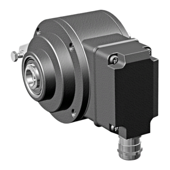
Incremental encoder, version with axial terminal cover
Hide thumbs
Also See for HOG 100:
- Mounting and operating instructions (32 pages) ,
- Mounting and operating instructions (32 pages)

Related Manuals for Baumer HOG 100


Summary of Contents for Baumer HOG 100
- Page 1 Montage- und Betriebsanleitung Installation and operating instructions HOG 100 Inkrementaler Drehgeber Version mit axialem Klemmendeckel Incremental Encoder Version with axial terminal cover...
-
Page 2: Table Of Contents
Inhaltsverzeichnis Inhaltsverzeichnis Allgemeine Hinweise ..............................Betrieb in explosionsgefährdeten Bereichen ..................... Sicherheitshinweise ..............................Vorbereitung ..................................Lieferumfang ................................ Zur Montage erforderlich (nicht im Lieferumfang enthalten) ............Zur Demontage erforderlich (nicht im Lieferumfang enthalten) ..........Erforderliches Werkzeug (nicht im Lieferumfang enthalten) ............Montage ..................................... - Page 3 Table of contents Table of contents General notes ................................... Operation in potentially explosive environments ..................Security indications ..............................Preparation ..................................Scope of delivery ............................... Required for mounting (not included in scope of delivery) ............Required for dismounting (not included in scope of delivery) ............
-
Page 4: Allgemeine Hinweise
Information Empfehlung für die Produkthandhabung Der inkrementale Drehgeber HOG 100 ist ein opto-elektronisches Prä zi sionsmessgerät, das mit Sorgfalt nur von technisch qualifiziertem Per sonal gehandhabt werden darf. Die zu erwartende Lebensdauer des Gerätes hängt von den Kugellagern ab, die mit einer Dauerschmierung ausgestattet sind. -
Page 5: General Notes
Information Recommendation for product handling The incremental encoder HOG 100 is an opto electro nic precision measurement device which must be handled with care by skilled personnel only. The expected operating life of the device depends on the ball bearings, which are equipped with a permanent lubrication. -
Page 6: Betrieb In Explosionsgefährdeten Bereichen
Betrieb in explosionsgefährdeten Bereichen Betrieb in explosionsgefährdeten Bereichen Das Gerät entspricht der Norm EG-Richtlinie 2014/34/EU für explosionsgefährdete Bereiche. Der Einsatz ist gemäß den Gerätekategorien 3 G (Ex-Atmosphäre Gas) und 3 D (Ex-Atmosphäre Staub) zulässig. Gerätekategorie 3 G: - Ex-Kennzeichnung: II 3 G Ex nA IIC T4 Gc - Normenkonformität: EN 60079-0:2012 + A11:2013 EN 60079-15:2010... -
Page 7: Operation In Potentially Explosive Environments
Operation in potentially explosive environments Operation in potentially explosive environments The device complies with the EU standard 2014/34/EU for potentionally explosive atmospheres. It can be used in accordance with equipment categories 3 G (explosive gas atmosphere) and 3 D (explosive dust atmosphere). Equipment category 3 G: - Ex labeling: II 3 G Ex nA IIC T4 Gc... -
Page 8: Sicherheitshinweise
Sicherheitshinweise Sicherheitshinweise Verletzungsgefahr durch rotierende Wellen Haare und Kleidungsstücke können von rotierenden Wellen erfasst werden. • Vor allen Arbeiten alle Betriebsspannungen ausschalten und Maschinen stillsetzen. Zerstörungsgefahr durch elektrostatische Aufladung Die elektronischen Bauteile im Drehgeber sind empfindlich gegen hohe Spannungen. • Steckkontakte und elektronische Komponenten nicht berühren. •... -
Page 9: Security Indications
Security indications Security indications Risk of injury due to rotating shafts Hair and clothes may become tangled in rotating shafts. • Before all work switch off all operating voltages and ensure machinery is stationary. Risk of destruction due to electrostatic charge Electronic parts contained in the encoder are sensitive to high voltages. -
Page 10: Vorbereitung
Vorbereitung / Preparation Vorbereitung Preparation Lieferumfang Scope of delivery axial Gehäuse Housing Einseitig offene Hohlwelle oder Konuswelle Blind hollow shaft or cone shaft with spanner mit Schlüsselfläche SW 17 mm flat 17 mm a/f Spannelement (nur bei einseitig offener Hohlwelle) Clamping element (only for blind hollow shaft) NORD-LOCK Scheibe NL6 SP SS NORD-LOCK washer NL6 SP SS Befestigungsschraube M6x30, ISO 4762... -
Page 11: Zur Montage Erforderlich (Nicht Im Lieferumfang Enthalten)
Vorbereitung / Preparation Zur Montage erforderlich Required for mounting (nicht im Lieferumfang enthalten) (not included in scope of delivery) 21b 21c 3x 3x Drehmomentstütze, als Zubehör erhältlich, Torque arm, available as accessory, Bestellnummer (Länge L, Version): order number (length L, version): 11043628 (67-70 mm, Standard) 11043628... -
Page 12: Zur Demontage Erforderlich (Nicht Im Lieferumfang Enthalten)
Vorbereitung / Preparation Zur Demontage erforderlich Required for dismounting (nicht im Lieferumfang enthalten) (not included in scope of delivery) Demontageset als Zubehör erhältlich, Dismounting kit available as accessory, Bestellnummer 11077087, bestehend aus: order number 11077087, including: Gewindestift M6x10, ISO 7436 (5,8 Vzk) Setscrew M6x10, ISO 7436 (5.8 Vzk) Zylinderschraube M8x45, ISO 4762 (A2) Cylinder screw M8x45, ISO 4762 (A2) -
Page 13: Montage
Montage / Mounting Montage Mounting Schritt 1 Step 1 10 mm 10 mm Schritt 2 Step 2 3 mm * Siehe Seite 7 und 8 See page 7 and 8 MB156a - 11069623 Baumer_HOG100-R_II_DE-EN (17A1) ... -
Page 14: Schritt 3 - Version Mit Einseitig Offener Hohlwelle
Montage / Mounting Schritt 3 - Version mit einseitig offener Step 3 - Blind hollow shaft version Hohlwelle Zentrierbohrung Center hole DIN 332-D, M6x16 mm 53 mm 12 * 52 mm (40-52 mm) 1.6x8 mm 16 mm * Siehe Seite 7 und 8 See page 7 and 8 Motorwelle einfetten! Lubricate motor shaft! -
Page 15: Schritt 3 - Version Mit Konuswelle
Montage / Mounting Schritt 3 - Version mit Konuswelle Step 3 - Cone shaft version Zentrierbohrung Center hole DIN 332-D, M6x16 mm 1:10 12 * 1.6x8 mm * Siehe Seite 7 und 8 See page 7 and 8 Motorwelle einfetten! Lubricate motor shaft! Die Antriebswelle sollte einen mög- The drive shaft should have as less... -
Page 16: Schritt 4
Montage / Mounting Schritt 4 Step 4 Zul. Anzugsmoment bei Version mit einseitig offener Hohlwelle: Max. tightening torque for blind hollow shaft version: = 6 Nm Zul. Anzugsmoment bei Version mit Konuswelle: Max. tightening torque for cone shaft version: = 3-4 Nm 17 mm 5 mm 10 mm... -
Page 17: Schritt 5 - Drehmomentstütze
Montage / Mounting Schritt 5 - Drehmomentstütze Step 5 - Torque arm Die Montage der Drehmomentstütze sollte The torque arm should be mounted spielfrei erfolgen. Ein Spiel von beispiels- free from clearance. A play of just weise ±0,03 mm entspricht einem Rund- ±0.03 mm, results in concentricity lauffehler des Drehgebers von 0,06 mm, error of the encoder of 0.06 mm. -
Page 18: Hinweis Zur Vermeidung Von Messfehlern
Montage / Mounting Hinweis zur Vermeidung von Messfehlern How to prevent measurement errors Für einen einwandfreien Betrieb des To ensure that the encoder operates cor- Drehgebers ist ein korrekter Anbau, ins- rectly, it is necessary to mount it accurately besondere auch der Drehmomentstütze, as described in section 5.1 to 5.6, which in- notwendig, wie beschrieben in Abschnitt cludes correct mounting of the torque arm. -
Page 19: Schritt 6 Und 7
Montage / Mounting Schritt 6 und 7 Step 6 and 7 Ansicht 10 * siehe Abschnitt 7.3. View see section 7.3. 17 * Kabelschirm Cable shield 17 mm ø5-9 mm Zur Gewährleistung der angegebenen To ensure the specified protection Schutzart sind nur geeignete Kabel- class of the device the correct cable durchmesser zu verwenden. -
Page 20: Anbauhinweis
Montage / Mounting 5.10 Anbauhinweis 5.10 Mounting instruction Wir empfehlen, den Sinus Drehgeber It is recommended to mount the sine so zu montieren, dass der Kabelan- encoder with cable connection facing schluss keinem direkten Wasserein- downward and being not exposed to tritt ausgesetzt ist. -
Page 21: Abmessungen
Abmessungen / Dimensions Abmessungen Dimensions Einseitig offene Hohlwelle Blind hollow shaft (74153, 74157, 74207) (74153, 74157, 74207) Drehrichtung positiv Positive rotating direction Um 90° versetzt gezeichnet Drawing 90° rotated Zubehör Accessory Option Konuswelle Cone shaft (74150, 74297) (74150, 74297) Drehrichtung positiv Positive rotating direction Um 90°... -
Page 22: Elektrischer Anschluss
Elektrischer Anschluss / Electrical connection Elektrischer Anschluss Electrical connection Beschreibung der Anschlüsse Terminal significance Betriebsspannung (für den Drehgeber) +UB; + Voltage supply (for the encoder) Masseanschluss (für die Signale) ; ; GND; 0V Ground (for the signals) Erdungsanschluss (Gehäuse) Earth ground (chassis) Ausgangssignal Kanal 1 K1;... -
Page 23: Klemmenbelegung
(inputs and outputs). Sensorkabel HEK 8 (Zubehör) Sensor cable HEK 8 (accessory) Es wird empfohlen, das Baumer Hübner Baumer Hübner sensor cable HEK 8 is Sensorkabel HEK 8 zu verwenden oder recommended. As a substitute a shielded ersatzweise ein geschirmtes, paarig ver- twisted pair cable should be used. -
Page 24: Demontage
Demontage / Dismounting Demontage Dismounting Schritt 1 Step 1 3 mm 17 mm 17 * * Siehe Seite 7 oder 8 See page 7 or 8 MB156a - 11069623 Baumer_HOG100-R_II_DE-EN (17A1) -
Page 25: Schritt 2
Demontage / Dismounting Schritt 2 Step 2 10 mm 12 * 1.6x8 mm Schritt 3 Step 3 17 mm 5 mm * Siehe Seite 7 oder 8 See page 7 or 8 MB156a - 11069623 Baumer_HOG100-R_II_DE-EN (17A1) ... -
Page 26: Schritt 4
Demontage / Dismounting Schritt 4 Step 4 0.8x4 mm Schritt 5 Step 5 17 mm 6 mm Schritt 6 Step 6 * Siehe Seite 8 See page 8 MB156a - 11069623 Baumer_HOG100-R_II_DE-EN (17A1) -
Page 27: Zubehör
Zubehör / Accessories Zubehör Accessories • Drehmomentstütze Größe M6 • Torque arm size M6 Bestellnummer: order number: siehe Abschnitt 4.3 see section 4.3 • Montageset für • Mounting kit for Drehmomentstütze Größe M6 torque arm size M6 und Erdungsband, and earthing strap, Bestellnummer: 11077197 order number: 11077197 •... -
Page 28: Technische Daten
Technische Daten Technische Daten 10.1 Technische Daten - elektrisch • Betriebsspannung: 9...30 VDC (HTL) 9...26 VDC (TTL - Version R) 5 VDC ±5 % (TTL) • Betriebsstrom ohne Last: ≤100 mA • Impulse pro Umdrehung: 1024...10000 (Je nach Bestellung) • Phasenverschiebung: 90°... -
Page 29: Technical Data
Technical data Technical data 10.1 Technical data - electrical ratings • Voltage supply: 9...30 VDC (HTL) 9...26 VDC (TTL - version R) 5 VDC ±5 % (TTL) • Consumption w/o load: ≤100 mA • Pulses per revolution: 1024...10000 (As ordered) • Phase shift: 90°... -
Page 30: Anhang: Eu-Konformitätserklärung
Signature/nom/fonction Baumer_HOGx_OGx_POGx_FOGx_HMI_DE-EN-FR_CoC_81201236.docm/kwe Baumer Hübner GmbH P.O. Box 126943 ∙ D-10609 Berlin ∙ Max-Dohrn-Str. 2+4 ∙ D-10589 Berlin Phone +49 (0)30 69003-0 ∙ Fax +49 (0)30 69003-104 ∙ info@baumerhuebner.com ∙ www.baumer.com Sitz der Gesellschaft / Registered Office: Berlin, Germany ∙ Geschäftsführer / Managing Director: Dr. Oliver Vietze, Dr. Johann Pohany Handelsregister / Commercial Registry: AG Charlottenburg HRB 96409 ∙... - Page 31 MB156a - 11069623 Baumer_HOG100-R_II_DE-EN (17A1) ...
- Page 32 Baumer Hübner GmbH P.O. Box 12 69 43 · 10609 Berlin, Germany Phone: +49 (0)30/69003-0 · Fax: +49 (0)30/69003-104 info@baumerhuebner.com · www.baumer.com/motion Version: 74150, 74153, 74157, 74207, 74297 MB156a - 11069623 Baumer_HOG100-R_II_DE-EN (17A1 - 29.05.2017)
Need help?
Do you have a question about the HOG 100 and is the answer not in the manual?
Questions and answers