Table of Contents

Related Manuals for Vestil SL Series


Summary of Contents for Vestil SL Series
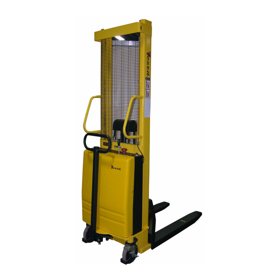
- Page 1 OPERATION & SERVICE MANUAL SL SERIES SEMI-ELECTRIC STACKER WITH MANUAL DRIVE & POWERED LIFT Vestil Manufacturing Corp. 2999 North Wayne St., Angola, IN 46703 Ph: 260-665-7586 Fax: 260-665-1339 E-mail: Sales@vestil.com Website: www.vestil.com...
-
Page 2: Table Of Contents
General ………………………………………………………………………………… Specification …………………………………………………… Receiving instructions ……………………………………………………………… Safety Notes ……….…………………………………………………………………… Product description ……………………………………………………………… Designated use …. … …... … ……………………………………………………. Signs on the Truck ………………………………………………………………… Removing from the pallet ……………………………………………………… Operation ……………………………………………………………………………. Operation ……………………………………………………………………………. Operating elements ……………………………………………………………….. Traveling ……………………………………………………………………………. Lifting and lowering ………… ……………………………………………………. Parking Brake ………………………………………………………………………... - Page 3 Introduction Read and follow the instructions contained in this operating manual. Only trained, well-informed personnel, who have been instructed in accordance with this operation manual, may use or work on the stacker. Liability or guarantee is waived if: The instructions in this operating manual are not observed. The high-lift stacking truck is operated, cleaned or maintained incorrectly.
-
Page 4: Specification
Specification SPECIFICATION SL-63-AA/FF SL-118-AA/FF SL-137-AA 2000 lbs. 2000 lbs. 2000 lbs. Capacity 63” 118” 137” Fork Lift Height b)1500 lbs. @ (63-118”) 2000 lbs. @ 63” 1500 lbs (63”-118”) Capacity c)1000 lbs. @ (118-137”) Fork Dimension 42x5.9 x2 3/8” 42x5.9x2 3/8” None 42x4 x1 ¼”... -
Page 5: Receiving Instructions
Receiving Instructions Every unit is thoroughly tested and inspected prior to shipment. However, it is possible that the unit may incur damage during transit. If you see damage when unloading, make a note of it on the SHIPPER RECEIVER. Remove all packing & strapping material, inspect for damage. IF DAMGE IS EVIDENT, FILE A CLAIM WITH THE CARRIER IMMEDIATELY! Also, check fork size, type of power unit, etc., to see that the unit is correct for the intended application. -
Page 6: Safety Notes
Safety notes Symbols and pictures In addition to the text and illustrations, this operating manual contains various symbols which should draw attention to the safety requirements. They generally have the following appearance: Signal wording Explanation DANGER Warning of an imminent danger! Non-observance cause death or serious injury Warning of a possibly incoming dangerous situation. -
Page 7: Product Description
Product description Designated use The stacker is designated for lifting, lowering and transportation of loads according to the specifications of the identification plate. The stacker is to be used on hard level surfaces. To move the stacker between buildings, warehouses etc The gradient of the slope must not be more than 10% Make sure load is not loose or unstable. - Page 8 Product description Signs on the Stacker...
-
Page 9: Removing From The Pallet
Removing from the pallet CAREFUL To pick up the unit only use overhead hoist, or forklift with sufficient carrying capacity & take into consideration the center of gravity of the unit. Use top crossmember to lift the equipment. Be careful of the stacker swinging once fully lifted off the pallet or skid. Remove the pallet or skid from below the lift &... -
Page 10: Operation
OPERATION Visually inspect stacker for damaged and worn parts, before stacker is taken into operation. Authorized person should read and understand all instructions The lifting truck is ready for immediate use once the packaging has been removed. The battery is full and charged. The hydraulic tank is full. -
Page 11: Operation
Operation Operating Elements... -
Page 12: Traveling
Traveling... -
Page 13: Lifting And Lowering
To raise and lower The following are generally valid for the lifting and lowering procedure: The red operating button of the EMERGENCY STOP pushbutton must be pulled upwards Lifting and lowering movements are initiated by pushing & pulling a lever on the power unit. -
Page 14: Parking Brake
Operation PARKING BRAKE To activate the parking brake, press down on the brake pedal To release the parking brake, press down on the brake pedal... - Page 15 LEG ADJUSTMENT Step 1: Lift the stacker around 1" from ground. This is to take pressure off of the legs. Step 2: Loosen three nuts on one side of the stacker Step 3: Loosen three socket head bolts. Use 12mm allen wrench to loosen the bolts.
-
Page 16: Lifting & Transporting The Load
Operation Lifting the load CAUTION! Before lifting a load to be transported, ensure that the load does not exceed carrying capacity of the stacker. The nominal carrying capacity and lifting heights can be viewed in the load diagram. Ensure that the load can be lifted up in a compact and stable manner. Slipping or falling of the load must be avoided. -
Page 17: Maintenance And Repair
Maintenance and repair -- ______ ROUBLESHOOTING UIDE Warning: Before performing any task, always block drive wheel off of the ground. Consult the factory for problems at time of installation, or for any problems not addressed below. Problem: Possible cause(s): Action: Unit will not charge Charger malfunction Verify output voltage on charger,... - Page 18 the unit does not lower, remove the connector to the coil and measure the coil resistance. It should be around 39 ohms. If it’s open, or shorted replace the coil. Upper limit switch out of Loosen hydraulic line at pump to adjustment relieve pressure build up.
- Page 19 Filename: Changing Batteries in SL Stacker VESTIL MFG. CO. Model: SL-63/118/137-AA/FF Instructions for Changing the Batteries, estimated time, 15 min. READ ALL INSTRUCTIONS BEFORE PROCEEDING! Only qualified personnel should work on this equipment! Lock out all potential energy sources before attempting this installation; turn off the unit and remove the key.
-
Page 20: Troubleshooting
Troubleshooting: If the unit does not operate, check all of the wiring connections to make sure they’re both mechanically and electrically sound – specifically at the battery, and the motor. A fully-charged lead acid battery in good condition at room temperature should read 12.65 volts. At 11.9 volts it is considered to be fully discharged and in need of charging. - Page 21 Maintenance and repair (A) BEFORE EACH USE INSPECT FOR THE FOLLOWING: 1) Frayed wires 2) Oil leaks 3) Pinched or chafed hoses 4) Damage or structural deformation to the structural members, the cylinder brackets, etc. 5) Unusual noise or binding, or evidence thereof. 6) Proper functioning of all limit switches, including those on the perimeter pinch point guard (if applicable) 7) Load chain, check for mechanical damage, check for play (slack in chain) 8) Battery, keep the surface of battery clean and dry.
-
Page 22: Maintenance And Care Of The Load Chains
Maintenance and repair Maintenance and care of the load chains In normal use the load chains should be re-lubricated every 250 operating hours; in the event of heavy soiling, moisture and very high prolonged loading, re-lubrication should be effected after 100 operating hours. If subject to corrosive media the chain should be cleaned and lubricated immediately. -
Page 23: Chain Inspections
Maintenance and repair Chain inspections Chains used in stackers should be inspected at least once a year or every three months if exposed to severe contamination or high continuous loading stress. We recommend that attention be paid to the following points: 1. -
Page 24: Temporary Lay-Up
Maintenance and repair Temporary lay-up If, for operating reasons, the stacker is laid up for more than two months, the following instructions are to be carried out: Place the stacker on blocks so that all the wheels are raised from the floor. In this way, they will be prevented from becoming permanently misshapen. -
Page 25: Warranty
Angola, Indiana. Who may request service? Only the warrantee may request service. You are a warrantee if you purchased the product from Vestil or from an authorized distributor AND Vestil has been fully paid. What is covered under the warranty? The warranty covers the following original drive and lift components: drive motors and lift motors, hydraulic pumps, electronic controllers, switches and cylinders. -
Page 26: Parts Drawing & Parts List
PARTS DRAWING & PARTS LIST Electric wiring diagram... - Page 27 Electric circuit diagram and component list Name Code Specification Power meter DC12V Lift motor DC12v/1.5KW Battery 12V/135Ah Lift motor contactor MZJ200S 12V FS-10 10A Control circuit fuse Hydraulic circuit fuse 200A Key switch JT-001 Emergency stop ZDK31-250 Lift limit switch TM1703 Lift micro switch YBLXW-5/11M...
- Page 28 Hydraulic circuit diagram...
- Page 30 Parts list Assembly component list...
- Page 31 Parts drawing & Parts list Inner mast drawing...
- Page 32 Parts drawing & Parts list Fork drawing...
- Page 33 Parts drawing Steering assembly drawing 2019...
- Page 34 Parts list Steering assembly component list...
Need help?
Do you have a question about the SL Series and is the answer not in the manual?
Questions and answers