
Subscribe to Our Youtube Channel
Related Manuals for Beckhoff PS1111-2402-0002


Summary of Contents for Beckhoff PS1111-2402-0002
- Page 1 Documentation | EN PS1111-2402-0002 Power supply 24 V DC, 2.5 A, 1-phase 2020-10-27 | Version: 1.0...
-
Page 3: Table Of Contents
4 Application notes............................. 26 Charging batteries ........................... 26 Series connection .......................... 26 Parallel use to increase power ...................... 26 Operation on two phases......................... 26 Use in a tightly sealed enclosure ..................... 27 5 Appendix .............................. 28 Documentation issue status ...................... 28 Support and Service ........................ 29 PS1111-2402-0002 Version: 1.0... - Page 4 Table of contents Version: 1.0 PS1111-2402-0002...
-
Page 5: Overview
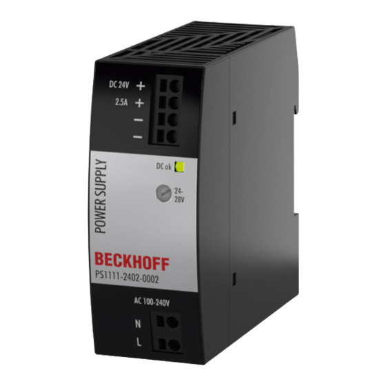
• Full power between -10°C and +60°C • Push-in terminals The PS1111-2402-0002 power supply is a single-phase 24V power supply with an output current of 2.5A. On the input side, the device has a wide-range input and an input inrush current limitation. -
Page 6: Foreword
, XFC , XTS and XPlanar are registered trademarks of and licensed by Beckhoff Automation GmbH. Other designations used in this publication may be trademarks whose use by third parties for their own purposes could violate the rights of the owners. -
Page 7: Safety Instructions
All the components are supplied in particular hardware and software configurations appropriate for the application. Modifications to hardware or software configurations other than those described in the documentation are not permitted, and nullify the liability of Beckhoff Automation GmbH & Co. KG. Personnel qualification This description is only intended for trained specialists in control, automation and drive engineering who are familiar with the applicable national standards. - Page 8 Foreword Safety instructions and installation requirements for the PS1111-2402-0002 power supply DANGER Danger of electric shock, fire, injuries, injuries resulting in death! • Do not use the power supply without proper grounding (protective conductor). Use the terminal at the in- put terminal strip for the earth connection, not one of the screws on the housing.
-
Page 9: Terminology And Abbreviations
50 Hz. AC 120 V parameters are valid for a mains frequency of 60 Hz. A keyword indicating a choice without implied preference. shall A keyword indicating a mandatory requirement. should A keyword indicating a choice with a clearly preferred method of implementation. PS1111-2402-0002 Version: 1.0... -
Page 10: Technical Data, Mounting, Wiring
*) The power factor is the ratio of real (or active) power to apparent power in an AC circuit. Fig. 1: Input voltage range; switch-on behavior definitions Fig. 2: Input current over output current; power factor over output current Version: 1.0 PS1111-2402-0002... -
Page 11: Dc Input
Technical data, mounting, wiring DC input Do not operate this power supply with DC input voltage! PS1111-2402-0002 Version: 1.0... -
Page 12: Input Inrush Current
Inrush energy Max. 0.2A 0.3A 1.4A At +40°C, cold start Fig. 3: Switch-on behavior at nominal load, typ., 120Vac@25°C; zoom inrush current surge Fig. 4: Switch-on behavior at nominal load, typ., 230Vac@25°C; zoom inrush current surge Version: 1.0 PS1111-2402-0002... -
Page 13: Output
It does not matter whether the power supply is switched on or off. The absorbed energy can be calculated by means of the built-in large-size output capacitor. Fig. 5: Output voltage over output current, typ.; short circuit at the output. PS1111-2402-0002 Version: 1.0... -
Page 14: Hold-Up Time
Min. 11ms 19ms 90ms At 24V, 2.5A, see Fig. Hold-up time over input voltage Min. 30ms 46ms 184ms At 24V, 1.25A, see Fig. Hold-up time over input voltage Fig. 6: Hold-up time over input voltage; switch-off behavior, definitions Version: 1.0 PS1111-2402-0002... -
Page 15: Efficiency And Losses
75% of the nominal load during 25% of the time and 100% of the nominal load during the remaining time. Fig. 7: Efficiency over output current; losses over output current Fig. 8: Efficiency over input voltage; losses over input voltage PS1111-2402-0002 Version: 1.0... -
Page 16: Functional Wiring Diagram
Technical data, mounting, wiring Functional wiring diagram Fig. 9: Functional wiring diagram Version: 1.0 PS1111-2402-0002... -
Page 17: Front Side And Operating Elements
Potentiometer for the output voltage Designation (C) Description Potentiometer Factory setting: 24.1 V DC-OK LED Designation (D) Description LED green Lights up when the output voltage is above 18V. PS1111-2402-0002 Version: 1.0... -
Page 18: Terminals And Wiring
AWG 24-12 (AWG) f*: AWG 24-12 f*: AWG 24-12 a* AWG 24-12 (d<2.3mm) a* AWG 24-12 (d<2.3mm) Strip length 10mm / 0.4inch 10mm / 0.4inch e* = solid wire f* = stranded wire a* = with ferrule Version: 1.0 PS1111-2402-0002... -
Page 19: Lifetime Expectancy
803,000h At 24V, 2.5A and 40°C; Ground Benign GB40 217F 1,257,000h 1,278,000h 1,175,000h At 24V, 2.5A and 25°C; Ground Benign GB25 247,000h 252,000h 247,000h At 24V, 2.5A and 40°C; Ground Fixed GF40 325,000h 331,000h 328,000h At 24V, 2.5A and 25°C; Ground Fixed GF25 PS1111-2402-0002 Version: 1.0... -
Page 20: Emc
Operation is subject to the following two conditions: (1) This device may not cause harmful interference, and (2) this device must be able to deal with any interference received, including interference that may cause undesired operation. Switching frequencies Main converter 40kHz to 140kHz Input load and output voltage dependent Version: 1.0 PS1111-2402-0002... -
Page 21: Environment
The derating is not hardware-controlled. The user must take this into account in order to stay below the reduced current limits, so that device overload is avoided. Fig. 11: Output current over ambient temperature; output current over installation altitude PS1111-2402-0002 Version: 1.0... -
Page 22: Protective Functions And Safety Features
At 230Vac, 50Hz, TN, TT / IT network Max. 60µA / 100µA At 110Vac, 50Hz, TN, TT / IT network Max. 80µA / 150µA At 132Vac, 60Hz, TN, TT / IT network Max. 140µA / 260µA At 264Vac, 50Hz, TN, TT / IT network Version: 1.0 PS1111-2402-0002... -
Page 23: Dielectric Strength
Setting the cut-off current > 2mA We recommend connecting either the positive or the negative pole to the protective conductor system. This avoids situations in which the load starts unexpectedly or cannot be disconnected if an unnoticed earth leakage occurs. PS1111-2402-0002 Version: 1.0... -
Page 24: Declaration Of Conformity And Approvals
Technical data, mounting, wiring 3.16 Declaration of conformity and approvals EU declaration of conformity UL Certificate: UL 61010-1/2-201 Applicable for US and Canada UL Certificate: NEC Class 2 Version: 1.0 PS1111-2402-0002... -
Page 25: Dimensions And Weight
High-quality polycarbonate/ABS blend material Installation clearances See chapter on Safety instructions and installation requirements [} 8] Ingress protection Small parts such as screws, nuts etc. with a diameter of more than 4.2 mm. Fig. 13: Front/side view PS1111-2402-0002, all specifications in mm PS1111-2402-0002 Version: 1.0... -
Page 26: Application Notes
Do not connect devices for higher output currents in parallel. Operation on two phases The power supply can also be used on two phases of a three-phase system. Such a phase-to-phase connection is permissible as long as the supply voltage is below 240V+10%. Version: 1.0 PS1111-2402-0002... -
Page 27: Use In A Tightly Sealed Enclosure
IP66 PK 9516 100, plastic PK 9516 100, plastic Input voltage 230Vac 230Vac Load 24V, 2A; (=80%) 24V, 2.5A; (=100%) Temperature inside 28.6°C 30.2°C the housing Temperature outside 21.0°C 21.0°C the housing Temperature 7.6K 9.2K increase PS1111-2402-0002 Version: 1.0... -
Page 28: Appendix
Appendix Appendix Documentation issue status Version Comment - First public issue - Corrections and addenda - Preliminary documentation for PS1111-2402-0000 Version: 1.0 PS1111-2402-0002... -
Page 29: Support And Service
Please contact your Beckhoff branch office or representative for local support and service on Beckhoff products! The addresses of Beckhoff's branch offices and representatives round the world can be found on her internet pages: https://www.beckhoff.com/english/beckhoff/world.htm You will also find further documentation for Beckhoff components there. - Page 31 More Information: www.beckhoff.com/ps1111-2402-0002 Beckhoff Automation GmbH & Co. KG Hülshorstweg 20 33415 Verl Germany Phone: +49 5246 9630 info@beckhoff.com www.beckhoff.com...
Need help?
Do you have a question about the PS1111-2402-0002 and is the answer not in the manual?
Questions and answers