
Subscribe to Our Youtube Channel
Related Manuals for Beckhoff PS2031-2410-0000


Summary of Contents for Beckhoff PS2031-2410-0000
- Page 1 Documentation | EN PS2031-2410-0000 Power supply 24 V DC, 10 A, 3-phase 2020-10-08 | Version: 1.0...
-
Page 3: Table Of Contents
Charging batteries ........................... 31 Series connection .......................... 31 Parallel use to increase power ...................... 31 Operation on two phases......................... 32 Use in a tightly sealed enclosure ..................... 33 Installation positions ........................ 34 5 Appendix .............................. 36 Accessories ............................. 36 Documentation issue status ...................... 38 Support and Service ........................ 39 PS2031-2410-0000 Version: 1.0... - Page 4 Table of contents Version: 1.0 PS2031-2410-0000...
-
Page 5: Overview
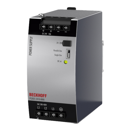
• Current-sharing function for parallel use • Full output between -25°C and +60°C The PS2031-2410-0000 is a 3-phase 24 V power supply unit with an output current of 10 A and an output power of 240 W. On the input side, the device features a wide-range input, harmonic correction (PFC) and inrush current limitation. -
Page 6: Foreword
, XFC , XTS and XPlanar are registered trademarks of and licensed by Beckhoff Automation GmbH. Other designations used in this publication may be trademarks whose use by third parties for their own purposes could violate the rights of the owners. -
Page 7: Safety Instructions
All the components are supplied in particular hardware and software configurations appropriate for the application. Modifications to hardware or software configurations other than those described in the documentation are not permitted, and nullify the liability of Beckhoff Automation GmbH & Co. KG. Personnel qualification This description is only intended for trained specialists in control, automation and drive engineering who are familiar with the applicable national standards. - Page 8 Foreword Safety instructions and installation requirements for PS2031-2410-0000 power supply unit DANGER Danger of electric shock, fire, injuries, injuries resulting in death! • Do not use the power supply without proper earthing (protective conductor). Use the terminal at the input terminal strip for the earth connection, not one of the screws on the housing.
- Page 9 • The maximum ambient air temperature is +70°C (+158°F). The operating temperature corre- sponds to the ambient or ambient air temperature, per definition at 2 cm below the device. • The device is designed for operation in the relative humidity range between 5% and 95%. PS2031-2410-0000 Version: 1.0...
-
Page 10: Terminology And Abbreviations
Unless otherwise specified, AC 230 V parameters are valid at a mains frequency of 50 Hz. A keyword indicating a choice without implied preference. shall A keyword indicating a mandatory requirement. should A keyword indicating a choice with a clearly preferred method of implementation. Version: 1.0 PS2031-2410-0000... -
Page 11: Technical Data, Mounting, Wiring
200 mV 200 mV See Fig. Input voltage range; switch-on behavior defini- tions *) The power factor is the ratio of real (or active) power to apparent power in an AC circuit. Fig. 1: Input voltage range; switch-on behavior definitions PS2031-2410-0000 Version: 1.0... - Page 12 Technical data, mounting, wiring Fig. 2: Input current over output current; power factor over output current Version: 1.0 PS2031-2410-0000...
-
Page 13: Dc Input
Technical data, mounting, wiring DC input Do not use the power supply unit with DC input voltages! PS2031-2410-0000 Version: 1.0... -
Page 14: Input Inrush Current
3AC 400V 3AC 480V Input inrush Max. 10A temperature-independent peak peak current Typ. 4A peak peak Inrush energy Max. 0.5A²s 0.5A²s Fig. 3: Typical switch-on behavior at nominal load, 25°C ambient temperature Version: 1.0 PS2031-2410-0000... -
Page 15: Output
This current is also available for temperatures up to +70°C with a duty cycle of 10% and/or no more than 1 minute every 10 minutes. Fig. 4: Output voltage over output current (single use); output voltage over output current (parallel use). PS2031-2410-0000 Version: 1.0... -
Page 16: Hold-Up Time
At 24V, 5A, see Fig. Hold-up time over input voltage Min. 28ms 44ms At 24V, 10A, see Fig. Hold-up time over input voltage Min. 56ms 87ms At 24V, 5A, see Fig. Hold-up time over input voltage Fig. 5: Hold-up time over input voltage; switch-off behavior, definitions Version: 1.0 PS2031-2410-0000... -
Page 17: Efficiency And Losses
75% of the nominal load during 25% of the time and 100% of the nominal load during the remaining time. Fig. 6: Efficiency over output current; losses over output current Fig. 7: Efficiency over input voltage; losses over input voltage PS2031-2410-0000 Version: 1.0... -
Page 18: Lifetime Expectancy
At 24V, 5A and +40°C, 2-phase operation 36,000h 42,000h At 24V, 12A and +40°C, 2-phase operation 135,000h 164,000h At 24V, 10A and +25°C, 2-phase operation 379,000h 410,000h At 24V, 5A and +25°C, 2-phase operation 102,000h 119,000h At 24V, 12A and +25°C, 2-phase operation Version: 1.0 PS2031-2410-0000... -
Page 19: Mtbf
GB40 555,000h 572,000h At 24V, 10A and 25°C, 2-phase operation, Ground Benign GB25 98,000h 98,000h At 24V, 10A and 40°C, 2-phase operation, Ground Fixed GF40 129,000h 129,000h At 24V, 10A and 25°C, 2-phase operation, Ground Fixed GF25 PS2031-2410-0000 Version: 1.0... -
Page 20: Terminals And Wiring
25 A. For higher currents please use a separate distributor terminal strip as shown in Fig. Using distribution terminals. Fig. 8: Series connection of outputs; use of distribution terminals Version: 1.0 PS2031-2410-0000... -
Page 21: Functional Wiring Diagram
Technical data, mounting, wiring 3.10 Functional wiring diagram Fig. 9: Functional wiring diagram PS2031-2410-0000 Version: 1.0... -
Page 22: Front Side And Operating Elements
Technical data, mounting, wiring 3.11 Front side and operating elements Fig. 10: Front PS2031-2410-0000 Input terminals (screw terminals) Designation (A) Description L1, L2, L3 Mains input L1, L2, L3 PE input (protective conductor) Output terminals (screw terminals) Designation (B) Description two identical positive poles, positive output... -
Page 23: Emc
Operation is subject to the following two conditions: (1) This device may not cause harmful interference, and (2) this device must be able to deal with any interference received, including interference that may cause undesired operation. Tested with constant current loads, non-pulsating Switching frequencies Main converter 80kHz to 140kHz Output load and input voltage dependent PS2031-2410-0000 Version: 1.0... -
Page 24: Environment
2cm below the device. Tested in conjunction with DIN rails according to EN 60715 with a height of 15mm and a thickness of 1.3mm and standard mounting position. Fig. 11: Output current over ambient temperature; output current over installation altitude Version: 1.0 PS2031-2410-0000... -
Page 25: Protective Functions
Leakage current Typ. 0.17mA With 3x 400Vac, 50Hz, TN, TT network Typ. 0.24mA With 3x 480Vac, 60Hz, TN, TT network Max. 0.22mA With 3x 440Vac, 50Hz, TN, TT network Max. 0.31mA With 3x 528Vac, 50Hz, TN, TT network PS2031-2410-0000 Version: 1.0... -
Page 26: Dielectric Strength
This avoids situations in which the load starts unexpectedly or cannot be disconnected if an unnoticed earth leakage occurs. Fig. 12: Dielectric strength Type test 2500Vac 3000Vac 500Vac Component test 2500Vac 2500Vac 500Vac Field test 2000Vac 2000Vac 500Vac Setting the cut-off current > 10mA > 10mA > 30mA Version: 1.0 PS2031-2410-0000... -
Page 27: Declaration Of Conformity And Approvals
Technical data, mounting, wiring 3.17 Declaration of conformity and approvals EU declaration of conformity UL Certificate: UL 508, Applicable for US and Canada PS2031-2410-0000 Version: 1.0... -
Page 28: Dimensions And Weight
Housing: Aluminum alloy Cover: Galvanized steel Ingress protection Small parts such as screws, nuts, etc. with a diameter greater than 3.5 mm Installation clearances See chapter on Safety instructions and installation requirements [} 9] Fig. 13: Front/side view PS2031-2410-0000 Version: 1.0 PS2031-2410-0000... -
Page 29: Application Notes
The capacitors are discharged during such an event, which leads to a voltage drop at the output. The following two examples show typical voltage drops for ohmic loads: Fig. 14: 20A peak current for 50ms, typ. (2x nominal current) Fig. 15: 50A peak current for 5ms, typ. (5x nominal current) PS2031-2410-0000 Version: 1.0... -
Page 30: Output Circuit Breakers
2.5mm C-2A C-3A C-4A C-6A C-8A C-10A 0.75mm 1.0mm 1.5mm 2.5mm B-6A B-10A B-13A Don't forget to double the distance to the load (or the cable length) when calculating the total cable length (plus and minus cable). Version: 1.0 PS2031-2410-0000... -
Page 31: Charging Batteries
Parallel use to increase power PS2031-2410-0000 power supplies can be connected in parallel to increase the output power. The output voltage of all power supplies must be set to the same value (±100mV) in "Single Use" mode and with the same load conditions on all devices, or the factory settings of the devices can be retained. -
Page 32: Operation On Two Phases
Therefore check the suitability of your individual application. The use of only two strands of a three-phase system is not covered by the official approval. Therefore, additional examinations may be required during the approval process of the final system. Version: 1.0 PS2031-2410-0000... -
Page 33: Use In A Tightly Sealed Enclosure
The temperature sensor inside the box is placed at the center of the right side of the power supply at a distance of 1 cm. The following measurement results can be used as a reference to estimate the temperature rise within the enclosure. PS2031-2410-0000 Version: 1.0... -
Page 34: Installation Positions
The values for service life and MTBF given in this data sheet are only valid for the standard mounting orientation. The following curves give an indication of permissible output currents for altitudes up to 2000m. Fig. 22: Mounting position A (standard mounting position) Fig. 23: Mounting position B (upside down) Fig. 24: Mounting position C (table mounting) Version: 1.0 PS2031-2410-0000... - Page 35 Application notes Fig. 25: Mounting position D (horizontal clockwise) Fig. 26: Mounting position E (horizontal counterclockwise) PS2031-2410-0000 Version: 1.0...
-
Page 36: Appendix
The two aluminum brackets and the black plastic slider of the device must be removed to allow the steel brackets to be mounted. For lateral DIN rail mounting, the previously removed aluminum brackets and the plastic slider must be mounted on the steel bracket. For more information please refer to the ZS5301-0006 documentation. Version: 1.0 PS2031-2410-0000... - Page 37 Appendix Fig. 29: Mounting information Fig. 30: Lateral mounting with and without DIN rail brackets Fig. 31: Installation dimensions Angle for side mounting PS2031-2410-0000 Version: 1.0...
-
Page 38: Documentation Issue Status
Appendix Documentation issue status Version Comment - First public issue - Complements, corrections - Complements, corrections - Preliminary documentation for PS2031-2410-0000 Version: 1.0 PS2031-2410-0000... -
Page 39: Support And Service
Please contact your Beckhoff branch office or representative for local support and service on Beckhoff products! The addresses of Beckhoff's branch offices and representatives round the world can be found on her internet pages: https://www.beckhoff.com/english/beckhoff/world.htm You will also find further documentation for Beckhoff components there. - Page 41 More Information: www.beckhoff.com/ps2031-2410-0000 Beckhoff Automation GmbH & Co. KG Hülshorstweg 20 33415 Verl Germany Phone: +49 5246 9630 info@beckhoff.com www.beckhoff.com...
Need help?
Do you have a question about the PS2031-2410-0000 and is the answer not in the manual?
Questions and answers