
Related Manuals for Beckhoff PS1011-2420-0000


Summary of Contents for Beckhoff PS1011-2420-0000
- Page 1 Documentation | EN PS1011-2420-0000 Power supply 24 V DC, 20 A, 1-phase 2020-10-27 | Version: 1.0...
-
Page 3: Table Of Contents
4 Application notes............................. 27 Charging batteries ........................... 27 Series connection .......................... 27 Parallel use to increase power ...................... 27 Operation on two phases......................... 27 Use in a tightly sealed enclosure ..................... 28 5 Appendix .............................. 29 Documentation issue status ...................... 29 Support and Service ........................ 30 PS1011-2420-0000 Version: 1.0... - Page 4 Table of contents Version: 1.0 PS1011-2420-0000...
-
Page 5: Overview
• Full power between -25°C and +55°C • DC-OK relay contact The PS1011-2420-0000 is a 1-phase 24 V power supply with an output current of 20 A and an output power of 480 W. On the input side, the device features a wide-range input, active power factor correction (PFC) and inrush current limiting. -
Page 6: Foreword
, XFC , XTS and XPlanar are registered trademarks of and licensed by Beckhoff Automation GmbH. Other designations used in this publication may be trademarks whose use by third parties for their own purposes could violate the rights of the owners. -
Page 7: Terminology And Abbreviations
50 Hz. AC 120 V parameters are valid for a mains frequency of 60 Hz. A keyword indicating a choice without implied preference. shall A keyword indicating a mandatory requirement. should A keyword indicating a choice with a clearly preferred method of implementation. PS1011-2420-0000 Version: 1.0... -
Page 8: Safety Instructions
All the components are supplied in particular hardware and software configurations appropriate for the application. Modifications to hardware or software configurations other than those described in the documentation are not permitted, and nullify the liability of Beckhoff Automation GmbH & Co. KG. Personnel qualification This description is only intended for trained specialists in control, automation and drive engineering who are familiar with the applicable national standards. - Page 9 Foreword Safety instructions and installation requirements for the PS1011-2420-0000 power supply DANGER Danger of electric shock, fire, injuries, injuries resulting in death! • Do not use the power supply without proper grounding (protective conductor). Use the terminal at the in- put terminal strip for the earth connection, not one of the screws on the housing.
-
Page 10: Technical Data, Mounting, Wiring
The crest factor is the mathematical ratio of the peak value over the RMS value of the input current waveform. Fig. 1: Input voltage range; switch-on behavior definitions Fig. 2: Input current over output current; power factor over output current Version: 1.0 PS1011-2420-0000... -
Page 11: Dc Input
Technical data, mounting, wiring DC input Do not operate this power supply with DC input voltage! PS1011-2420-0000 Version: 1.0... -
Page 12: Input Inrush Current
Inrush energy Max. 3A²s 3A²s 3A²s At +40°C, cold start Fig. 3: Switch-on behavior at nominal load, typ., 120Vac@25°C; zoom inrush current surge Fig. 4: Switch-on behavior at nominal load, typ., 230Vac@25°C; zoom inrush current surge Version: 1.0 PS1011-2420-0000... -
Page 13: Output
2-5 seconds. The output is then switched off for approx. 7 second before a new start attempt is automatically made for 1 second. This cycle is repeated as long as the overload exists. The device starts operating normally again once the overload has been rectified. Fig. 5: Output voltage over output current, typ.; short circuit at the output. PS1011-2420-0000 Version: 1.0... -
Page 14: Hold-Up Time
27ms 27ms 27ms At 24V, 20A, see Fig. Hold-up time over input voltage Min. 22ms 22ms 22ms At 24V, 20A, see Fig. Hold-up time over input voltage Fig. 6: Hold-up time over input voltage; switch-off behavior, definitions Version: 1.0 PS1011-2420-0000... -
Page 15: Dc-Ok Relay Contact
Contact load capacity Maximum 60Vdc 0.3A, 30Vdc 1A, 30Vac 0.5A, ohmic load Minimum permissible load: 1mA at 5Vdc Insulation voltage See the dielectric strength table in the chapter on Safety features [} 23] Fig. 7: Behavior of the DC-OK relay contact PS1011-2420-0000 Version: 1.0... -
Page 16: Efficiency And Losses
75% of the nominal load during 25% of the time and 100% of the nominal load during the remaining time. Fig. 8: Efficiency over output current; losses over output current Fig. 9: Efficiency over input voltage; losses over input voltage Version: 1.0 PS1011-2420-0000... -
Page 17: Functional Wiring Diagram
Technical data, mounting, wiring Functional wiring diagram Fig. 10: Functional wiring diagram PS1011-2420-0000 Version: 1.0... -
Page 18: Front Side And Operating Elements
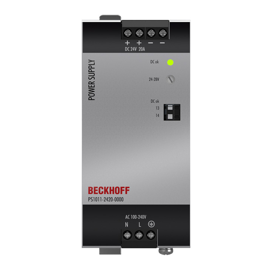
Technical data, mounting, wiring Front side and operating elements Fig. 11: Front PS1011-2420-0000 Input terminals (screw terminals) Designation (A) Description Mains input N Mains input L Protective conductor, PE Output terminals (screw terminals) Designation (B) Description two identical positive poles, positive output... -
Page 19: Terminals And Wiring
AWG 24-16 a* AWG 20-10 (d<2.8mm) a* AWG 20-10 a*: AWG 24-16 (d<2.8mm) (d<1.6 mm) Strip length 7mm / 0.28inch 7mm / 0.28inch 7mm / 0.28inch e* = solid wire f* = stranded wire a* = with ferrule PS1011-2420-0000 Version: 1.0... -
Page 20: Lifetime Expectancy
At 24V, 20A and 40°C; Ground Benign GB40 217F 368,000h 370,000h 386,000h At 24V, 20A and 25°C; Ground Benign GB25 59,000h 59,000h 63,000h At 24V, 20A and 40°C; Ground Fixed GF40 76,000h 76,000h 80,000h At 24V, 20A and 25°C; Ground Fixed GF25 Version: 1.0 PS1011-2420-0000... -
Page 21: Emc
Switching frequencies PFC converter 80kHz to 130kHz Input load and output voltage dependent Main converter 75kHz to 180kHz Output voltage and output load dependent Auxiliary converter 60kHz fixed frequency PS1011-2420-0000 Version: 1.0... -
Page 22: Environment
Tested in conjunction with DIN rails according to EN 60715 with a height of 15mm and a thickness of 1.3mm and standard mounting position. Fig. 12: Output current over ambient temperature; output current over installation altitude Version: 1.0 PS1011-2420-0000... -
Page 23: Protective Functions And Safety Features
At 230Vac, 50Hz, TN, TT / IT network Max. 0.15mA / 0.38mA At 110Vac, 50Hz, TN, TT / IT network Max. 0.21mA / 0.56mA At 132Vac, 60Hz, TN, TT / IT network Max. 0.35mA / 0.91mA At 264Vac, 50Hz, TN, TT / IT network PS1011-2420-0000 Version: 1.0... -
Page 24: Dielectric Strength
(column D). We recommend connecting the DC-OK pins and the output pins when performing the test. Type test 2500Vac 3000Vac 500Vac 500Vac Component test 5s 2500Vac 2500Vac 500Vac 500Vac Field test 2000Vac 2000Vac 500Vac 500Vac Setting the cut-off current > 10mA > 10mA > 20mA > 1mA Version: 1.0 PS1011-2420-0000... -
Page 25: Declaration Of Conformity And Approvals
Technical data, mounting, wiring 3.17 Declaration of conformity and approvals EU declaration of conformity UL Certificate: UL 61010-1/2-201 Applicable for US and Canada PS1011-2420-0000 Version: 1.0... -
Page 26: Dimensions And Weight
Cover: Galvanized steel Installation clearances See chapter on Safety instructions and installation requirements [} 9] Ingress protection Small parts such as screws, nuts etc. with a diameter of more than 4.5 mm. Fig. 14: Front/side view PS2001-2410-0000, all specifications in mm Version: 1.0 PS1011-2420-0000... -
Page 27: Application Notes
Do not connect devices for higher output currents in parallel. Operation on two phases The power supply can also be used on two phases of a three-phase system. Such a phase-to-phase connection is permissible as long as the supply voltage is below 240V+10%. PS1011-2420-0000 Version: 1.0... -
Page 28: Use In A Tightly Sealed Enclosure
IP66 PK 9516 100, plastic PK 9516 100, plastic Input voltage 230Vac 230Vac Load 24V, 16A; (=80%) 24V, 20A; (=100%) Temperature inside 48.3°C 55.3°C the housing Temperature outside 21.0°C 21.0°C the housing Temperature 27.3K 34.3K increase Version: 1.0 PS1011-2420-0000... -
Page 29: Appendix
Appendix Appendix Documentation issue status Version Comment - First public issue - Corrections and addenda - Preliminary documentation for PS1011-2420-0000 PS1011-2420-0000 Version: 1.0... -
Page 30: Support And Service
Please contact your Beckhoff branch office or representative for local support and service on Beckhoff products! The addresses of Beckhoff's branch offices and representatives round the world can be found on her internet pages: https://www.beckhoff.com/english/beckhoff/world.htm You will also find further documentation for Beckhoff components there. - Page 32 More Information: www.beckhoff.com/ps1011-2420-0000 Beckhoff Automation GmbH & Co. KG Hülshorstweg 20 33415 Verl Germany Phone: +49 5246 9630 info@beckhoff.com www.beckhoff.com...
Need help?
Do you have a question about the PS1011-2420-0000 and is the answer not in the manual?
Questions and answers