CS Instruments DS 500 Modbus Installation And Operating Instructions
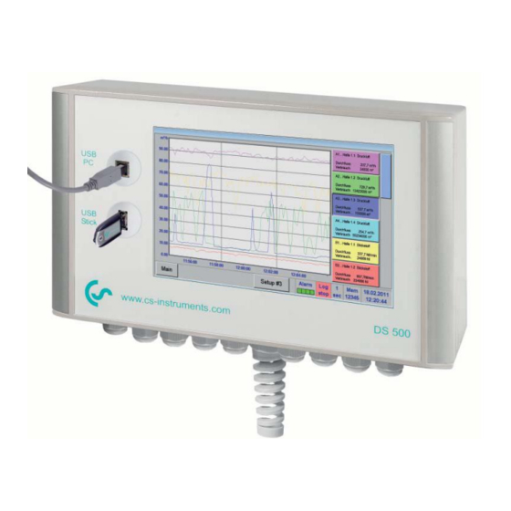
Intelligent paperless recorder
Hide thumbs
Also See for DS 500:
- Installation and operating instructions manual (124 pages) ,
- Installation and operating instructions manual (66 pages) ,
- Installation and operating instructions manual (36 pages)

Related Manuals for CS Instruments DS 500


Summary of Contents for CS Instruments DS 500
- Page 1 EN - English Modbus Installation and operating instructions Intelligent paperless recorder DS 500 DS 500 V1.13 Side 1 of 50...
-
Page 2: Foreword
Foreword Dear customer, thank you very much for deciding in favour of the DS 500. Please read this installation and operation manual carefully before mounting and initiating the device and follow our advice. A riskless operation and a correct functioning of the DS 500 are only guaranteed in case of careful observation of the described instructions and notes. -
Page 3: Table Of Contents
Foreword ........................2 Safety instructions ......................5 Instructions ........................5 Definition and abbreviation ....................6 References ..........................6 Technical data DS 500 ....................6 DS500 MODBUS RTU specification..................6 DS500 MODBUS/ TCP Specification ..................7 General Modbus Information ....................7 3.3.1 Serial transmission modes (RTU) .................. - Page 4 APPENDIX A - Exception codes ..................50 DS 500 V1.13 Side 4 of 50...
-
Page 5: Safety Instructions
This instruction manual has to be available at any time at the operation site of the DS 500. Regional and national regulations respectively, have to be observed in addition to this instruction manual if necessary. -
Page 6: Definition And Abbreviation
This manual is intended to provide instructions for the installation and use of the DS 500 MODBUS function. The DS 500 MODBUS function can let the MODBUS master device to read out the online measurement values. This manual is not intended to be a complete tutorial on the MODBUS RTU protocol, and it is assumed the end user already has a general working knowledge of MODBUS RTU Communications, especially in respect of master station configuration and operation. -
Page 7: Ds500 Modbus/ Tcp Specification
Modbus Messaging on TCP/IP Implementation Guide V1.0b General Modbus Information The DS 500 Modbus module complies with the Modbus serial line protocol [Reference 1]. Among other things this implies a master-slave protocol at level 2 of the OSI model. One node (the master) issues explicit commands to one of the ,,sIave"-nodes and processes... -
Page 8: 3.3.2 Ethernet Transmission Modes
Further details of the Modbus protocol can be found in Reference 1 and 2. 3.3.2 Ethernet transmission modes The DS 500 Modbus mode supports the Modbus/TCP only The transmission mode defines the bit contents of message fields transmitted serially on the line. -
Page 9: Installation
R120 configuration XA.1 - XA.4: sensor channels 1 – 4 X4.1 S4.1 RS485 HALF S2, S3, S7 ON TERMINATING 120R DS 500 version 8 7 6 5 4 3 2 1 Master Common DS500 Mainboard Slave n X4.1 Slave 1 5 4 3 2 1 S4.1... -
Page 10: Rs485 Bus Wiring (Modbus Rtu) - Connection Diagram Ds500V2
5 4 3 2 1 DS500V2 Mainboard Note: In case DS500V2 is the last device in the RS485 network then the termination should be switch on per software. Settings → Device settings → Modbus settings DS 500 V1.13 Side 10 of 50... -
Page 11: Bus Cable
Ethernet connection for Modbus/TCP For easy Ethernet cable connection to your network an ordinary RJ45 Ethernet cable connection is provided. Cable: An Ethernet cable with category 5 or better is to be used. DS 500 V1.13 Side 11 of 50... -
Page 12: Modbus Rtu Communication Settings
New password repeat in red font. If you can’t remember the password, please use Master password in order to enter a new password. Remark: The master password is supplied together with the instrument’s documentation. DS 500 V1.13 Side 12 of 50... - Page 13 In such a case, an abnormal behavior of the whole serial bus can occur, the master being then in the impossibility to communicate with all present slaves on the bus. DS 500 V1.13 Side 13 of 50...
-
Page 14: Modbus Tcp Communication Settings
By communication via Modbus TCP the Modbus Id have to be set only and confirmed by pressing Apply button. “Data Format” With the transmission type ABCD (Little Endian) or CDAB (Middle Endian) will be defined DS 500 V1.13 Side 14 of 50... -
Page 15: Modbus Addressing Model
UI2 (16b) = unsigned Integer => 65535 I2 (16b) = signed integer => -32768 - 32767 UI4 (32b) = unsigned Integer => 4294967295 I4 (32b) = signed integer => -2147483648 - 2147483647 R4 (32b) = Float DS 500 V1.13 Side 15 of 50... -
Page 16: Function Code 3 (Read Holding Register)
• If start-address is not the start of a mapped holding register => Exception 2 (Illegal data address) • Writing to holes is allowed (ie ignored - and no exception occurs) — except for the condition described above DS 500 V1.13 Side 16 of 50... -
Page 17: Modbus Holding Register
Modbus ID Word free free MbRTU Rx valid RTU telegrams Dword Packets OK received MbRTU Tx Dword RTU telegrams transmitted Packets MbRTU CRC Dword CRC Errors Errors MbRtu Parity Dword Parity Errors Errors DS 500 V1.13 Side 17 of 50... -
Page 18: Register Channel Values
Value A1-3 → Register 1004 (Consumtion) 5th Value Value A1-5 → Register 1200 (Temperature) Value A1-8 → Register 1206 (Velocity) 8th Value Arrangement VA5xx (with pressure) 1st Value 3rd Value 8th Value 5th Value 7th Value DS 500 V1.13 Side 18 of 50... -
Page 19: Register Channel Values 1
Channel B1 3rd 1037 1036 Float/Dword DS500 Data Value *1) value Channel B1 4th 1039 1038The Float/Dword DS500 Data Value *1) value Channel B2 1st 1041 1040 Float/Dword DS500 Data Value *1) value DS 500 V1.13 Side 19 of 50... - Page 20 Channel C3 2nd 1083 1082 Float/Dword DS500 Data Value *1) value 1085 1084 Float/Dword Channel C3 3rd DS500 Data Value *1) value 1087 1086 Float/Dword Channel C3 4th DS500 Data Value *1) value DS 500 V1.13 Side 20 of 50...
- Page 21 Channel V4 2nd 1123 1122 Float/Dword DS500 Data Value *1) value Channel V4 3rd 1125 1124 Float/Dword DS500 Data Value *1) value Channel V4 4th 1127 1126 Float/Dword DS500 Data Value *1) value DS 500 V1.13 Side 21 of 50...
-
Page 22: Register Values Channel 5
Channel B1 7th 1237 1236 Float/Dword DS500 Data Value *1) value Channel B1 8th 1239 1238 Float/Dword DS500 Data Value *1) value Channel B2 5th 1241 1240 Float/Dword DS500 Data Value *1) value DS 500 V1.13 Side 22 of 50... - Page 23 Channel C3 6th 1283 1282 Float/Dword DS500 Data Value *1) value 1285 1284 Float/Dword Channel C3 7th DS500 Data Value *1) value 1287 1286 Float/Dword Channel C3 8th DS500 Data Value *1) value DS 500 V1.13 Side 23 of 50...
- Page 24 Channel V4 6th 1323 1322 Float/Dword DS500 Data Value *1) value Channel V4 7th 1325 1324 Float/Dword DS500 Data Value *1) value Channel V4 8th 1327 1326 Float/Dword DS500 Data Value *1) value DS 500 V1.13 Side 24 of 50...
-
Page 25: Status Register
Value 2 Status Channel B1 2019 2018 word Status *2) Value 3 Status Channel B1 2020 2019 word Status *2) Value 4 Status Channel B2 2021 2020 word Status *2) Value 1 Status DS 500 V1.13 Side 25 of 50... - Page 26 Value 3 Status Channel C2 2040 2039 word Status *2) Value 4 Status Channel C3 2041 2040 word Status *2) Value 1 Status Channel C3 2042 2041 word Status *2) Value 2 Status DS 500 V1.13 Side 26 of 50...
- Page 27 Value 1 Status Channel V4 2062 2061 word Status *2) Value 2 Status Channel V4 2063 2062 word Status *2) Value 3 Status Channel V4 2064 2063 word Status *2) Value 4 Status DS 500 V1.13 Side 27 of 50...
-
Page 28: Status Register Values 5
Value 6 Status Channel B1 2119 2118 word Status *2) Value 7 Status Channel B1 2120 2119 word Status *2) Value 8 Status Channel B2 2121 2120 word Status *2) Value 5 Status DS 500 V1.13 Side 28 of 50... - Page 29 Value 7 Status Channel C2 2140 2139 word Status *2) Value 8 Status Channel C3 2141 2140 word Status *2) Value 5 Status Channel C3 2142 2141 word Status *2) Value 6 Status DS 500 V1.13 Side 29 of 50...
- Page 30 Value 5 Status Channel V4 2162 2161 word Status *2) Value 6 Status Channel V4 2163 2162 word Status *2) Value 7 Status Channel V4 2164 2163 word Status *2) Value 8 Status DS 500 V1.13 Side 30 of 50...
-
Page 31: Channel Description
Value description *5) value 7 name/unit index 3053 3052 word Value description *5) value 8 Channel A3 3065 3064 word Sensor Type *3) sensor type 3066 3065 string Channel Name Sensor Name *4) DS 500 V1.13 Side 31 of 50... - Page 32 Sensor Type *3) sensor type 3130 3129 string Channel Name Sensor Name *4) name/unit index 3142 3141 word Value description *5) value 1 name/unit index 3143 3142 word Value description *5) value 2 DS 500 V1.13 Side 32 of 50...
- Page 33 Sensor Name *4) name/unit index 3206 3205 word Value description *5) value 1 name/unit index 3207 3206 word Value description *5) value 2 name/unit index 3208 3207 word Value description *5) value 3 DS 500 V1.13 Side 33 of 50...
- Page 34 Value description *5) value 1 name/unit index 3271 3270 word Value description *5) value 2 name/unit index 3272 3271 word Value description *5) value 3 name/unit index 3273 3272 word Value description *5) value 4 DS 500 V1.13 Side 34 of 50...
- Page 35 Value description *5) value 2 name/unit index 3336 3335 word Value description *5) value 3 name/unit index 3337 3336 word Value description *5) value 4 name/unit index 3338 3337 word Value description *5) value 5 DS 500 V1.13 Side 35 of 50...
- Page 36 Value description *5) value 3 name/unit index 3401 3400 word Value description *5) value 4 name/unit index 3402 3401 word Value description *5) value 5 name/unit index 3403 3402 word Value description *5) value 6 DS 500 V1.13 Side 36 of 50...
- Page 37 Value description *5) value 4 name/unit index 3466 3465 word Value description *5) value 5 name/unit index 3467 3466 word Value description *5) value 6 name/unit index 3468 3467 word Value description *5) value 7 DS 500 V1.13 Side 37 of 50...
- Page 38 3499 word Value description *5) value 7 name/unit index 3501 3500 word Value description *5) value 8 32 registers = 64 byte for one channel (8 values); actually 21 registers used per channel DS 500 V1.13 Side 38 of 50...
-
Page 39: Alarm Settings
Hysteresis for 4029 4028 float above lower warning 4031 4030 float value Hysteresis for 4033 4032 float above lower alarm 4035 4034 float value Hysteresis for 4037 4036 float above 4039 4038 float Reserved DS 500 V1.13 Side 39 of 50... - Page 40 Channel / Value Alarmsettings #20 4401 4400 Channel / Value Alarmsettings #21 4421 4420 Channel / Value Alarmsettings #22 4441 4440 Channel / Value Alarmsettings #23 4461 4460 Channel / Value Alarmsettings #24 DS 500 V1.13 Side 40 of 50...
- Page 41 Channel / Value Alarmsettings #28 4561 4560 Channel / Value Alarmsettings #29 4581 4580 Channel / Value Alarmsettings #30 4601 4600 Channel / Value Alarmsettings #31 4621 4620 Channel / Value Alarmsettings #32 DS 500 V1.13 Side 41 of 50...
-
Page 42: Register Value Extended
10110 10109 word 0..5 Resolution 10111 10110 free A1e future use A1f Value Name 10126 10125 string string max 10 character long A1f Value Name 10132 10131 string string max 3 character short DS 500 V1.13 Side 42 of 50... - Page 43 Channel C1 similar to channel A1 11801 11800 8*25 Channel C2 similar to channel A1 12001 12000 8*25 Channel C3 similar to channel A1 12201 12200 8*25 Channel C4 similar to channel A1 DS 500 V1.13 Side 43 of 50...
-
Page 44: Data Format Test
Data format test Modbus Modbus No.of Default Read Data Type Description Comment Register Address Byte Setting Write 64001 64000 Dword 1000000 format test for Dword 64003 64002 float 1000000.0 format test for float DS 500 V1.13 Side 44 of 50... -
Page 45: Data Bit Description
Name coding in UTF8 (max 24 Byte) Value description 1 = Dword , 0 = float 14..12 position of dezimal point 0..7 11..7 index of value name 0..31 6..0 index of unit name 0..127 0 = value not used DS 500 V1.13 Side 45 of 50... - Page 46 Upper alarm Relais 3 used Upper alarm Relais 2 used Upper alarm Relais 1 used Upper warning Relais 4 used Upper warning Relais 3 used Upper warning Relais 2 used Upper warning Relais 1 used DS 500 V1.13 Side 46 of 50...
-
Page 47: User Units
UTF8 string (max 10 14153 14152 string Unit Name 20 Nm³/min character) UTF8 string (max 10 14161 14160 string Unit Name 21 Nl/min character) UTF8 string (max 10 14169 14168 string Unit Name 22 Nl/min character) DS 500 V1.13 Side 47 of 50... - Page 48 UTF8 string (max 10 14329 14328 string Unit Name 42 µV character) UTF8 string (max 10 14337 14336 string Unit Name 43 character) UTF8 string (max 10 14345 14344 string Unit Name 44 character) DS 500 V1.13 Side 48 of 50...
- Page 49 UTF8 string (max 10 14489 14488 string Unit Name 62 character) UTF8 string (max 10 € 14497 14496 string Unit Name 63 character) UTF8 string (max 10 15505 15504 String Unit Name 63 cts/m³ character) DS 500 V1.13 Side 49 of 50...
-
Page 50: Appendix
The DS500 Modbus uses the following exception codes when responding to the master Exception Code Exception name 0x01 Illegal function 0x02 Illegal data address 0x03 Illegal data value 0x04 Slave device failure 0x05 Acknowledge 0x06 Slave device busy DS 500 V1.13 Side 50 of 50...
Need help?
Do you have a question about the DS 500 and is the answer not in the manual?
Questions and answers