Table of Contents
Advertisement
Quick Links
Advertisement
Table of Contents

Related Manuals for CS Instruments VD 520


Summary of Contents for CS Instruments VD 520
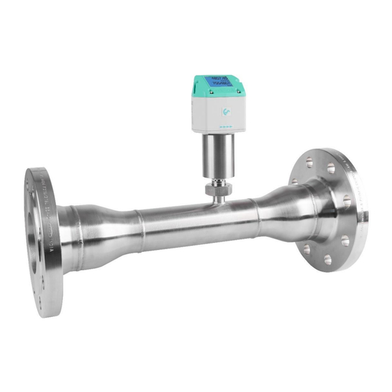
- Page 1 Operating instructions Flow sensor VD 520 VD 520 EN V1.00...
-
Page 2: Foreword
Fax: +49 (0) 461 807 150 15 Mail: info@cs-instruments.com Web: http://www.cs-instruments.com Imprint © CS Instruments GmbH & Co.KG | 24955 Harrislee | Gewerbehof 14 | GERMANY. Translated of German original manual VD 520 | DE | V1.00. VD 520 EN V1.00... -
Page 3: Table Of Contents
Reduced measuring section with welding neck flanges ......... 17 Installation preparations ................18 Positioning the flow sensor ................18 Necessary inlet and outlet sections ..............18 Installation VD 520 ..................20 10.1 Rotating the control unit ................. 20 Electrical connection ................... 21 11.1... - Page 4 Language ....................39 13.3.5.3 Display / Touch ..................40 13.3.6 Extended .......................40 13.3.7 4 -20mA ......................41 13.3.8 VD 520 Info ....................43 13.4 M-Bus ......................44 13.4.1 Change communication values ..............44 13.4.2 Coding VIF (Value Information Field) .............45 13.4.3 Basic communication settings ex works ............45 13.4.4...
-
Page 5: Scope Of Delivery
1. Scope of delivery 1 Scope of delivery • VD 520 flow sensor with integrated measuring section • Calibration certificate • These operating instructions 2 Type plate 1 - Manufacturer info 2 - Sensor name 3 - Order number, serial number, production date... -
Page 6: Device Overview
24VDC, Modbus RTU, 4...20 mA M12 panel connector A, 5-pin, A-coded: Switching output (pulse or alarm) Optional: Modbus TCP / PoE: D-coded or M-BUS Pressure measuring head Locking nut Measuring tip Measuring section Selection button (UP) ENTER/OK button Flow direction VD 520 EN V1.00... -
Page 7: Intended Use
4. Intended use 4 Intended use The VD 520 flow sensor is a measuring probe for measuring the flow and consumption of gaseous fluids (air, nitrogen, etc.) in pipelines (dynamic pressure/differential pressure measurement). Areas of application: Directly after the compressor (wet side), at high temperatures (up to 180 °C) and/or fast processes (approx. -
Page 8: Safety Regulations
▶ Failure to comply could result in serious injury or death. CAUTION Potentially dangerous situation! ▶ Non-compliance may result in moderate to minor injuries. NOTE Potentially dangerous situation! ▶ Failure to observe may result in damage to property. VD 520 EN V1.00... -
Page 9: General Safety Instructions
Duties of the system installer: The system installer is responsible for the safety of the system in which the VD 520 is installed. Pay particular attention to the technical data and ambient conditions (chapter 8) as well as the information on the electrical connection and prescribed connection cables (chapter 11). - Page 10 Risk of burns due to hot sensor shaft. Hot air/gas/gas mixtures in the pipe can heat or warm up the sensor shaft of the flow sensor. Only touch the sensor shaft when it has cooled down. Use protective gloves if necessary. VD 520 EN V1.00...
-
Page 11: Environmental Protection
DE: Disposal code according to the Waste Catalogue Ordinance (AVV) 16 02 14, electrical and electronic devices and their components. VD 520 EN V1.00... -
Page 12: Product Information
7. Product information 7 Product information 7.1 Product features The VD 520 flow sensor is a consumption meter for gaseous fluids (air, nitrogen, etc.). Advantages ● Integrated display with indication of flow rate, consumption, speed, temperature and pressure ● Units freely selectable: m³/h, m³/min, l/min, l/s, kg/h, kg/min, kg/s, cfm, bar, psi, °C or °F... -
Page 13: Technical Data
Electrical connection Protection class IP 65 * based on ISO 1217 with 1000 mbar / 14.50 psi at 20 °C / 68 °F v. M. = from measured value | v. E. = from final value VD 520 EN V1.00... -
Page 14: Measuring Range Values
8. Technical data 8.2 Measuring range values Measuring ranges VD 520 flow sensor for compressed air at (ISO 1217:1000 mbar, 20 °C) Pipe inner diameter 2...224 m/s Measuring range start/end values Customs m³/h (cfm) ¾" 21,7 DN 20 2...215 1,2...127 1"... -
Page 15: Dimensions
DN 40 48,3 / 41,9 241,4 R 1 1/2" 217,2 DN 50 60,3 / 53,1 247,4 R 2" 217,2 DN 65 76,1 / 68,9 255,3 R 2 1/2" 217,2 DN 80 88,9 / 80,9 261,6 R 3" VD 520 EN V1.00... -
Page 16: Measuring Section With Welding Neck Flanges
48,3 / 41,9 292,2 4 x 18 217,2 DN 50 60,3 / 53,1 299,7 217,2 4 x 18 DN 65 76,1 / 68,9 319,7 227,2 8 x 18 DN 80 88,9 / 80,9 327,2 227,2 8 x 18 VD 520 EN V1.00... -
Page 17: Reduced Measuring Section With Welding Neck Flanges
DN 65 DN65 - DN40 48,3 / 41,9 309,7 8 x 18 217,2 DN 80 DN80 - DN50 60,3 / 53,1 317,2 217,2 8 x 18 DN 100 DN100-DN65 76,1 / 68,9 344,7 8 x 22 227,2 VD 520 EN V1.00... -
Page 18: Installation Preparations
9. Installation preparations 9 Installation preparations 9.1 Positioning the flow sensor ● To ensure precise measurement results, the VD 520 must be installed correctly in the pipe. ● Only use correctly dimensioned seals that are suitable for the flow medium. - Page 19 T-piece 2 bends á 90° 20 x D 5 x D in one plane 2 bends á 90° 3-dimensional change of 35 x D 5 x D direction Shut-off valve 45 x D 5 x D VD 520 EN V1.00...
-
Page 20: Installation Vd 520
Installation by the customer is only permitted when the system is depressurized • Check whether the VD 520 is correctly installed in the measuring section, the flow direction arrow must point in the correct direction. >>> Flow >>> >>> Flow >>>... -
Page 21: Electrical Connection
If no connecting cable/pulse cable M 12 connector plug has been ordered, the sensor sor is Rear view supplied with M12 connectors. The (terminal side) user can connect the signals as shown in the connection diagram. VD 520 EN V1.00... -
Page 22: Ethernet (Optional Poe)
- Connector B (M12 X-coded 8-pin) Connector plug B Connection cable M12 X-coded 8-pin M12 X-coded to RJ45 Data lines: 1,2 and 3,4 PoE lines: 5.6 and 7.8 M12 x 1 Connection cable: Cat 6. *PoE: Power over Ethernet VD 520 EN V1.00... -
Page 23: Commissioning
1. Ensure that the flow sensor is connected correctly. 2. After connecting the power supply (initial start or after a reset) reset), the VD 520 flow sensor switches on and performs a device initialization approx. 2...3 seconds. 12.2 Zero point adjustment The VD 520 flow sensor measures the flow velocity (differential pressure principle) in the middle of the pipe. -
Page 24: Operation Vd 520
13 Operation VD 520 13 Operation VD 520 Note: Only for version with display "OK" ( ) "Up" ( The VA 500 is operated using the two capacitive buttons Up ) and Enter Information or changes can be made in all fields with a white background; the selection for input is indicated by a yellow background color. -
Page 25: Main Menu (Home)
Operation 13.1 Main menu (Home) 13.1.1 Initialization After switching on the VD 520, initialization takes place, see right, followed by the main menu. Flow sensor 13.2 Main menu after switching on en Gasart / S tatusm eld ung HW V ersio n Mo dbus ID S eiten-Nr. -
Page 26: Settings Menu
">" button and then select with the "OK" button 13.3.1.1 Input pipe inside diameter Cannot be changed (locked) with VD 520, as it is matched to the measuring section supplied with the corresponding pipe diameter. VD 520 EN V1.00... -
Page 27: Entering / Changing The Consumption Meter Reading
If the number of units cannot be displayed on a page, press the "<" button to go to the next page. Accept the selection by pressing the "OK" button twice. Procedure for all 4 measured variables is analogous VD 520 EN V1.00... -
Page 28: Setting The Reference Conditions
Press " " to increase the value by 1. Finish with "OK" and activate the next number position. Complete the entry by pressing the "OK" button The procedure for changing the reference temperature is the same. VD 520 EN V1.00... -
Page 29: Setting The Zero Point And Creep Suppression
12.2 "Zero point calibration". Zero point calibration must be performed under system pressure and without flow . Select the "Zero point" button and start calibration with "OK". Exit the menu with "Back" VD 520 EN V1.00... - Page 30 "Reset" resets the settings for button "Zero point" "Creep rate". Exit the menu with "Back" Select the menu item with the " " button and then select with the "OK" button. Exit the menu with "Back". VD 520 EN V1.00...
-
Page 31: Modbus Rtu
Operation 13.3.2 Modbus RTU 13.3.2.1 Setup The VD 520 flow sensor is equipped with an RS 485 interface (Modbus RTU). Before commissioning the sensor, the communication parameters • Modbus ID, baud rate, parity and stop bit must be set to enable communication with the Modbus master. -
Page 32: Modbus Tcp (Optional)
When reassembling, ensure that the housing seal is correctly seated, see also point 4.5. 13.3.3 Modbus TCP (optional) 13.3.3.1 Setup The VD 520 flow sensor is optionally equipped with a Modbus TCP interface (HW interface: M12 X-coded female connector). With this option, the sensor supports the Modbus TCP protocol for communication with SCADA systems. - Page 33 → Settings→ Network IP Address computer can be set up and established here. Note: With DHCP activated, the sensor can be automatically integrated into an existing network without manual configuration. Accept the settings by clicking "Save". VD 520 EN V1.00...
- Page 34 "OK" button. Change the values with the ">" button, accept values with the "OK" button. Proceed in the same way for "Sub network" and "Gateway". Accept the settings by clicking "Save". VD 520 EN V1.00...
- Page 35 Possible formats are "ABCD" (Big Endian) and "CDAB" (Middle Endian) Save the changes using the "Save" button. Select and confirm with the ">" "OK" buttons. Reset to the default settings by pressing "Set default values" VD 520 EN V1.00...
-
Page 36: Modbus Settings (2001
1181 1180 Float Flow in cfm 1189 1188 Float Flow in Ncfm 1197 1196 Float Flow in kg/h 1205 1204 Float Flow in kg/min 1213 1212 Float Flow in kg/s 1221 1220 Float Flow in kW VD 520 EN V1.00... - Page 37 / display Note: • For DS400 / DS 500 / hand-held devices - Modbus sensor data type "Data type R4-32" corresponds to "Data type float" • For additional/further Modbus values, see VA5xx_Modbus_RTU_TCP installation in the current version. VD 520 EN V1.00...
-
Page 38: Pulse /Alarm
Table 1 Maximum flow rates for pulse output Entries of pulse values that do not allow a display for the measuring range end value are not permitted. Entries are discarded and an error message is displayed. VD 520 EN V1.00... -
Page 39: User Settings
Settings→ Users. Language There are currently 4 integrated languages that can be selected using the ">" button. Activate the language by confirming with "OK" button. Exit the menu by selecting "Back" confirming with the "OK" button. VD 520 EN V1.00... -
Page 40: Display / Touch
10 seconds. 13.3.6 Extended To do this, call up the operating menu → Settings Advanced during this period by pressing "OK". "Factory reset" button can be used to reset the sensor to the factory settings. VD 520 EN V1.00... -
Page 41: -20Ma
"OK" button. → Settings 4-20mA→ Channel 1 The 4-20 mA analog output of the VD 520 sensor can be set individually. It is possible to select the measured values 0.000 m³/h "Temperature", "Velocity" "Flow rate"... - Page 42 "OK" button Accept the entries with "Save", discard the changes Remark: with "Cancel". Default setting VD 520 for analog output is Channel 1:0...max. flow rate [m³/h] Press "Back" to switch to the settings menu. VD 520 EN V1.00...
-
Page 43: Vd 520 Info
Operation 13.3.8 VD 520 Info Settings→ Info Brief description of the sensor data including the calibration data. The calibration conditions can also be found under Details. 20.0°C 53.1 mm 24.0°C VD 520 EN V1.00... -
Page 44: M-Bus
M-Bus Baud rate Selection values are 2400, 4800 and button 9600 baud (delivery value = 2400). Accept the entries by clicking "Save", discard the changes by clicking "Cancel". Press "Back" to switch to the settings menu. VD 520 EN V1.00... -
Page 45: Coding Vif (Value Information Field)
Value 3 with [unit]*: Gas temperature [°C] Value 4 with [unit]*: System pressure [bar] *All values can be changed / preset in production or changed / set on site using the CS Service Software (order no. 0554 2007) VD 520 EN V1.00... -
Page 46: Error Messages
13 Operation VD 520 14 Error messages 14.1 Error messages • Low Voltage If the supply voltage is less than 11V, the warning message "Low Voltage" is displayed. This means that the sensor can no longer work / measure properly and therefore no measured values for flow rate, consumption and speed are available. - Page 47 *** VA 520 *** *** VA 520 *** Not calibrated Pressure error Internal Error Internal Error Internal Error *** VA 520 *** deltaPressure error Internal Error Status messages: *** VA 520 *** Internal Error dP Range next cal. elapsed VD 520 EN V1.00...
-
Page 48: Declaration Of Conformity
15.declaration of conformity 15 Declaration of conformity DECLARATION OF CONFORMITY DECLARATION OF CONFORMITY CS Instruments GmbH & Co KG Gewerbehof 14, 24955 Harrislee Declare under our sole responsibility that the product Declare under our sole responsibility that the product consumption/flow sensor...
Need help?
Do you have a question about the VD 520 and is the answer not in the manual?
Questions and answers