
Related Manuals for Ingersoll-Rand ST1000M Series


Summary of Contents for Ingersoll-Rand ST1000M Series
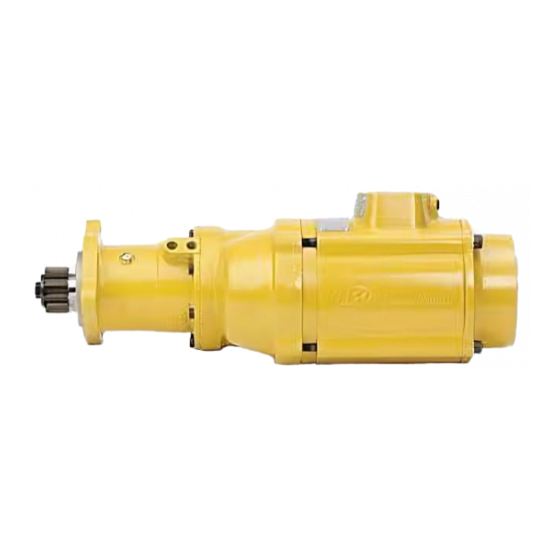
- Page 1 47113766 Edition 2 March 2012 Turbine Powered Starters Series ST1000M Installation and Maintenance Information Save These Instructions...
-
Page 2: Product Safety Information
Product Safety Information Intended Use: The ST1000M Series air starters are intended for use in starting reciprocating internal combustion engines. These starters are designed to be operated from a remote location after proper installation on the engine requiring starting. For additional information refer to Air Starters for Internal Combustion Engines Product Safety Information Manual Form 45558624. - Page 3 3. After the drive housing is properly oriented relative to the gear 8. Mount the 150 psi air pressure gauge 150 BMP-1064 on or case, determine if the inlet port will be favorably located for adjacent to the control panel. It should be located where it is hose installation.
-
Page 4: Performance Data
Performance Data ST1060M B Ratio Pressure Breakaway Torque Speed @ Max. Power Max. Power Flow @ Max. Power (psig) (lbf-ft) (rpm) (hp) (scfm) 1175 1550 1780 1900 1050 2050 1290 ST1099M B Ratio Pressure Breakaway Torque Speed @ Max. Power Max. - Page 5 Mounting Dimensions Pre-Engaged B & C Ratio : Elbow 596.87 Dual 23.499 Dimension 596.68 22.428 1/4” N.P.T “I” (IN) Control Port for engaging pinion. 226.02 292.86 Operating Pressure : 30-150 psig (207-1034 kPa) 8.898 11.530 1/4” N.P.T “O” (OUT) Control Port for actuation of main 222.50 air supply to starter motor.
- Page 6 Piping Diagrams Typical Single Starter Installation, Pre-engaged. Oil Pressure Sensing Valve Starter Solenoid Valve #4 Hose (1/4”) 150BMP-1051B (12V) #4 Hose (1/4”) 150BMP-2451B (24V) 2” Hose Optional with use of panel mounted switch. 2X JIC 37° #4 Hose (1/4”) JIC 37° Adapter Adapter 1/4”...
- Page 7 Standard High Pressure System when Supply Pressure is over Pressure Rating of Starter, Pre-Engaged. Relief valve set at Oil Pressure Sensing Valve 15 PSI above regulator setting Relay Valve 1½” #4 Hose (1/4”) SRV150 For gas operation, the relief JIC 37° Adapter valve outlet must be piped 1/4”...
- Page 8 Starter Orientation Pre-Engaged Starter Orientation Method Drive Housing Orientation Reference Feature Exhaust Orientation Reference Feature Inlet Orientation Reference Feature Orientation Shown : 2 2 G - Drive Housing (A - A-) Exhaust (0 - 3) Inlet (0 - 3) (Dwg. 45662434 SH1) 47113766_ed2...
- Page 9 Pinion Selection Table Gear Set Outer Diameter Pinion Code (from Rotation # Teeth Diametral Pitch Pressure Angle Part Number Ratio (mm) model number) B or C Right 57.15 20° SS825R-13-25 B or C Right 57.15 20° SS825R-13SR-25* B or C Right 57.15 20°...
- Page 10 Construction - Pre-Engaged ST1000M Turbine Starter (Pre-Engaged) (Dwg. 45660370 SH1) 47113766_ed2...
- Page 11 ST1000M Turbine Starter (Pre-Engaged) - Exploded Diagram (Dwg. 45659794) 47113766_ed2...
- Page 12 ST1000M Turbine Starter (Pre-Engaged) - Parts List Item Part Description Part Number Item Part Description Part Number Motor module Rotor pinion Right Hand Rotation, Straight Exhaust ST10_ _MR-37S* Right Hand Rotation ST1000L-17 Right Hand Rotation, Directional Exhaust ST10_ _MR-37D* Left Hand Rotation ST1000R-17 Left Hand Rotation, Straight Exhaust ST10_ _ML-37S*...
- Page 13 Item Part Description Part Number Item Part Description Part Number Drive shaft Pinion spring sleeve SS800-335 Right Hand Rotation SS800R-8 Drive pinion See “Drive Pinion Left Hand Rotation SS800L-8 Selection Chart” Rear drive shaft bearing SS800-399 Drive Pinion (R) Washer SS800-725 Drive shaft retainer SS800-209...
-
Page 14: Assembly And Installation
Lubrication NOTICE Each time an ST1000M series starter is disassembled for maintenance or repair, lubricate the starter as follows: On models with inertia drive, do not lubricate the threaded area of the drive shaft as it could collect dirt and foreign material For Models with Pre-Engaged Drive which will prevent efficient operation. - Page 15 Lubrication and Torque Specifications (Dwg. 45660370 SH2) 47113766_ed2...
- Page 16 Motor Module Removal and Disassembly 2. Using the punch ST1000-TL3, press one bearing (13) onto the adapter (27), slide the spacer (28) over the adapter, then press the 1. Remove both magnetic plugs (4) and drain the fluid from the other bearing (13) onto the adapter.
- Page 17 Idler Gear Set Removal and Disassembly Assembly and Installation 1. Remove the motor housing (1) from the intermediate gear case 1. Press one idler gear bearing (36) into an idler gear (35) followed (45) and the idler gear set from the motor housing. See by an idler gear spacer (37) and another idler gear bearing.
- Page 18 Drive Housing (Pre-Engaged) Removal and Disassembly 3. Press the rear drive shaft bearing (71) onto the drive shaft (70). 4 Slide the rear bearing retainer (72) convex side first onto the drive 1. Mark the orientation between the gear case (49) and drive shaft.
- Page 19 23. Remove the drive housing from the press. 28. Slide the pinion return spring (81) over the helical splines of the 24. Lubricate the drive housing O-Ring (78) with O-Ring lubricant drive shaft and the pinion spring sleeve (82) over the pinion and install it onto the drive housing.
-
Page 20: Retrofit Installation
The following instructions outline the necessary steps required to 2. Consult the SS800 manual (accessible from www. convert an ST900 or SS800 series starter to an ST1000M series starter. ingersollrandproducts.com) for instructions on separating the motor housing from the gear case. -
Page 21: Testing And Inspection
Testing and Inspection 1. Clutch ratcheting: Turn the drive shaft pinion (83) by hand in the 9. Drive housing function - pre-engaged models only: Apply direction of starter rotation. The clutch should ratchet smoothly 120 psig (8.2 bar/827 kPa) to the “I” (in) port of drive housing (79). with a slight clicking action. -
Page 22: Troubleshooting Guide
Troubleshooting Guide Trouble Probable Cause Solution No air supply. Check for blockage or damage to air supply lines or tank. Damaged motor assembly Inspect motor assembly and power train and repair or replace if necessary. Foreign material in motor and/or piping Remove motor assembly and/or piping and remove blockage. - Page 23 Notes:...
- Page 24 © 2012 Ingersoll-Rand Company...
Need help?
Do you have a question about the ST1000M Series and is the answer not in the manual?
Questions and answers