Table of Contents
Advertisement
Quick Links
Advertisement
Table of Contents

Related Manuals for Kimo KIGAZ 110


Summary of Contents for Kimo KIGAZ 110
-
Page 3: Table Of Contents
Table of contents ANALYSER 1. Introduction..............................7 1.1. Description of the gas analyser....................... 7 1.1.1. Overview of the gas analyser......................7 1.1.2. Presentation of the keypad and screen....................8 1.1.3. Connections of the analyser......................8 1.2. Main features............................9 1.3. Technical features..........................11 2. - Page 4 8.3. Delete an inspection..........................24 8.4. Create a group............................24 8.5. Add an inspection to a group.........................25 8.6. Delete a group............................25 9. Perform measurement of a customised procedure..................25 9.1. Preliminary operations to procedures....................25 9.2. Launch a customised procedure......................25 10. Perform a control of gas flow........................26 10.1.
- Page 5 21.1. Life-time of the sensors........................37 21.2. Replace the sensors..........................37 21.3. Replace the paper roll of the printer....................38 21.4. Replace the battery..........................39 22. Calculations of the different parameters......................39 22.1. CO and NO conversions........................39 22.2. Calculation of flue gas velocity......................39 SOFTWARE 1.
- Page 6 Introduction...
-
Page 7: Introduction
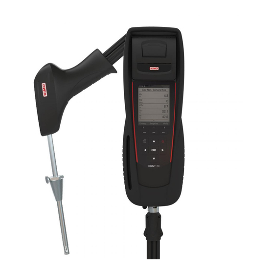
1.1. Description of the gas analyser The KIGAZ 110 is a gas analyser with two interchangeable sensors (long-life O and CO-H Its main features are the following: Sensors protection by pump stopping and configurable thresholds • Customers management • Creation and edition of inspections with the integrated printer •... -
Page 8: Presentation Of The Keypad And Screen
1.1.2. Presentation of the keypad and screen Measurement screen Function keys Esc button On/Off button Up arrow Right arrow Left arrow OK button Down arrow 1.1.3. Connections of the analyser C1 connection for external probe Flue gas probe connection Light for (Pt100 temperature, CH ,...) battery... -
Page 9: Main Features
Water trap • The water trap is placed on the tube that links the flue gas probe to the KIGAZ 110. The measured gases go through the filtering element allowing the recovery of condensates (liquid or solid one). The filtering element is placed 15 cm from the analyser and is divided into 2 parts:... - Page 10 When it s greater than sensible efficiency, then condensation is taking place. It is referred to LHV (Lower Heating Value) and can exceed 100%. The LHV is calculated by an algorithm developed by Kimo and its value must be considered as indicative. - CO (O ): Concentration of CO in flue gases in mg/m .
-
Page 11: Technical Features
1.3. Technical features response Parameter Sensor Measuring range Resolution Accuracy* time Long-life O Electro-chemical From 0 % to 21 % 0.1 % vol. ±0.2 % vol. 30 s From 0 to 200 ppm: ±10 ppm From 201 to 2000 ppm: (with H Electro-chemical From 0 to 8000 ppm 1 ppm... -
Page 12: Safety
• Therefore, it is forbidden to preserve or use these fluids nearby the analyser. Load the battery only with Kimo charger. The charger must be used only for the power supply loading. Use another • type of charger can damage the battery and the analyser and can cause electrical shocks. -
Page 13: Perform A Flue Gas Analysis
Empty the water trap. In case of any default or damage of the instrument, Kimo After sales service shall be contacted. On the back of the analyser, there is a label with the analyser serial number. This number shall be communicated for every operation (technical operation or request of spare parts). -
Page 14: Zoom Function
3.3. Zoom function From the gas analysis screen, the zoom function is available using the direction arrows. The initial screen displays 10 measured values. ➢ To zoom in, press the right arrow. The screen displays 5 measured values. ➢ To zoom in again, press the right arrow. The screen displays 2 measured values. -
Page 15: Perform A Quick Measurement
The quick measurement allows to perform in a few seconds: a flue gas measurement • a draft measurement • and an ambient CO measurement with Max CO. • ➢ During the quick measurement, it is possible to print a ticket at each step by pressing the “Print” function button, or print the whole measurements when the analyser proposes it at the end of the quick measurement (screen 14). -
Page 16: Set The Different Parameters Of The Analyser
The “Setting” menu allows to set the following parameters: Instrument (screen, printing, auto-off,...) • Combustibles • Measurement • References (O , atmospheric pressure and altitude) • Auto-zero/Purge • Operators • The “Setting” part allows to set parameters that can affect the performed measurements. These settings must be made by a qualified technician. -
Page 17: Ticket Printing Setting
5.1.5. Ticket printing setting “Setting > Instrument” screen is displayed. ➢ Go to “Printing” with the keypad then press OK. ➢ Go to “Format” with the keypad then press OK. ➢ Select the ticket format: long or short with the keypad then press OK. Long ticket format: prints the headers, the user name, Short ticket format: prints only the device reference, the type the type of device and its serial number, the customer and... -
Page 18: Activate The Group Function
5.1.7. Activate the group function Groups allow to gather measurements in a folder. To activate it: “Setting > Instrument” screen is displayed. ➢ Go to “Group” with the keypad. ➢ Press OK to activate it: ON or to deactivate it: OFF. For the groups creation and management, see page 24. -
Page 19: Add A Combustible
➢ Press the “OK” function key to validate the new combustible name. ➢ Press OK on the “Energy” line. ➢ Select the combustible energy type: solid, liquid or gas and press OK. ➢ Press the “Save” function key. The instrument backs to the combustible list with the modifications applied. 5.2.2. -
Page 20: Set The Co Protection Threshold
“Setting” menu is displayed. ➢ Go to “Measurement” with the keypad then press OK. ➢ Go to “Units” with the keypad then press OK ➢ Go to the parameter to modify with the keypad then press OK. The list of the available units according to the parameter appears. ➢... -
Page 21: Modify The Operator Name
➢ Press the “OK” function key to validate the operator name and to add it in the list. The analyser backs to the list of present operators. ➢ Press Esc to quit the screen. 5.6.2. Modify the operator name “Setting” screen is displayed. ➢... -
Page 22: Manage Customers
It is possible to save names and addresses of different customers in the analyser. The performed measurements could be assigned to them. It is possible to create up to 250 customers. 6.1. Manage a customer ➢ Turn on the analyser. ➢... -
Page 23: Manage Boilers
A boiler is compulsorily linked to a customer, at least one customer must be created to create a boiler. See page 22 for the creation of a customer. It is possible to link up to 10 boilers per customer. 7.1. Create a boiler The list of customers saved in the analyser is displayed. -
Page 24: Manage The Inspections
Each saved inspection is linked to a customer. It is possible to see the details of an inspection, to add one or to delete one. Available inspections in the analyser are the following: combustion, ambient temperature, flue gas temperature, internal temperature, Flow/Return temperature, dew-point temperature, draft pressure, differential pressure, flue gas velocity, Max CO, opacity, ambient CO ionisation current, leak detection, gas network tightness and gas flow. -
Page 25: Add An Inspection To A Group
➢ Go to the required group folder and press OK. The analyser displays the inspection list recorded in this group. ➢ Go to the required inspection and press OK. The analyser displays the inspections details. 8.5. Add an inspection to a group The group function has to be activated (see page 18). -
Page 26: Perform A Control Of Gas Flow
10.1. Perform a measurement of theoretical flow ➢ Turn on the analyser. Go to “Procedures” menu with the keypad then press OK. The analyser asks to select a customer: go to “OK” then press OK. The list of customers is displayed. ➢... -
Page 27: Perform A Gas Network Leak Test
To perform this test, it is necessary to have a gas network leak testing kit. This kit is available as option (ref: KEG). 11.1. Perform the test ➢ Connect the different items of the kit on the network to test (see user manual of the KEG). ➢... -
Page 28: Perform A Pressure Measurement
➢ Go to “Draft pressure” with the keypad then press OK. Measurement launches and the analyser displays the draft. Put the probe of the KIGAZ 110 in the Put the probe of the KIGAZ 110 in the Put the probe of the KIGAZ 110 in the... -
Page 29: Add The Measurement To A Group
12.5. Add the measurement to a group The group function has to be activated (see page 18). Once the measurement is linked to a customer and a boiler, it is possible to add it in a group in the instrument, or create a group: The analyser proposes to add the measurement to a group. -
Page 30: Perform A Measurement Of Max Co
14.1. Perform the measurement ➢ Connect a CO probe (available as option) on C1 connection on the top of the analyser or connect the flue gas probe on the single connector on the bottom of the analyser. ➢ Turn on the analyser. ➢... -
Page 31: Perform Some Temperature Measurements
15.1. Perform a measurement of ambient temperature ➢ Connect a Pt100 temperature probe (available as option) on C1 connection on the top of the analyser. ➢ Turn on the instrument. Home screen is displayed with measurement menu highlighted. ➢ Press OK. The analyser performs the auto-zero: remaining time and a progress bar are displayed on the screen. -
Page 32: Perform A Measurement Of Opacity
It is possible to enter in the analyser from 1 to 3 opacity indexes performed thanks to opacity pump available as option. The opacity index consists of the measurement of solid waste of combustion in the flue with a pump and a filter of measurement. The filter coloration is compared with a table reference composed by 10 greyed areas numbered from 0 to 9. -
Page 33: Perform A Measurement Of Ionisation Current
The measurement of ionisation current allows to check the presence of the flame. In standard operation, the ionisation probe produces a currant of a few µA or a few dozen of µA. In case of lack of flame, this current is not present anymore (measurement: 0 µA), the safety equipments of the boiler cut off the power supply. -
Page 34: Perform A Ch Measurement
18.1. Perform the measurement with the probe ➢ Connect a CH probe on C1 connection on the bottom of the analyser. ➢ Turn on the analyser. ➢ Go to the “Measurement” menu with the keypad then press OK. The analyser performs the autozero: remaining time and a progress bar are displayed on the screen. However it is possible to reach the gas leak detection menu during the autozero. -
Page 35: Perform A Flue Gas Velocity Measurement With A Pitot Tube
The used Pitot tube must be a Pitot tube type L with K thermocouple connection. The Pitot tube must be introduced perpendicularly, in the middle into the duct and parallel to the flow. The head (ending with an ellipsoidal nose) must be maintained parallel and facing the flow. -
Page 36: To Get To Information About The Analyser
Version of the firmware • Serial number of the analyser • The adjustment date • Phone and fax numbers, e-mail of Kimo Instruments • Options of the analyser • Type of sensor, its serial number and its installation date. •... -
Page 37: Maintenance Of The Analyser
As their consumption increases, features of the sensor are getting worse until their exhaustion, after which it is necessary to replace it. To ensure the measurement accuracy, sensors have to be calibrated only in Assistance centre qualified by Kimo. Sensor... -
Page 38: Replace The Paper Roll Of The Printer
sensor location CO sensor location Insertion of a new sensor then rotation Connection of the of the sensor sensor ribbon cable Exercise the pressure on the sensor body and not on the electronic card. Sensors have very accurate locations, see below locations defined for each sensor: Long-life O sensor must be in O position... -
Page 39: Replace The Battery
21.4. Replace the battery Follow this procedure to replace the battery: The analyser must be turned off. ➢ Remove the protective cover. ➢ Turn the analyser. ➢ Unscrew the battery cover with a cross-head screwdriver. ➢ Remove the battery cover. ➢... - Page 41 Calculations of the different parameters...
-
Page 42: Introduction
LIGAZ-2 software, supplied with the gas analysers of the KIGAZ range, allows to set the analyser, to create and give information a customers, boilers and inspections database, to process and download measurement datasets. 2.1. Recommended minimum configuration For the proper functioning of the software, the following minimum configuration is recommended: Operating system: Windows, XP, VISTA, 7 •... -
Page 43: Start With The Software
After double-clicking on the software launching icon on the desktop, the homepage of the software opens: 3.1. Meaning and functions of the menus bar (1) ➢ File Back to homepage: reduce all the opened windows • Save database: save the database into the computer •... -
Page 44: Meaning And Functions Of Tool Bar Buttons (2)
3.2. Meaning and functions of tool bar buttons (2) Back to homepage: closes all the opened windows Opens the boilers database window • • Opens the complete database window • Opens the analyser download window • (Customers, Boilers, Inspections) • Opens the customer database window Opens the analyser setting window •... -
Page 45: Use The Different Databases
Databases are used to give information about features of boilers and customers. LIGAZ-2 software allows to recover customers and boilers created in the analyser and allows to transfer customers and boilers created with LIGAZ-2 software in the analyser. ➢ Launch the software by double-clicking on the icon in the desktop. -
Page 46: Use The Boilers Database
➢ To download customers from the analyser to the software database, it is necessary to download inspections present on the device (see page 54). Only the customers linked to an inspection are added to the “Customers” software database. The boilers linked to this customer are also added to the “Boilers” software database. ➢... - Page 47 ➢ Click on the button in front of “Combustible” and select the combustible type of the boiler. The following window is displayed: ➢ Select the combustible used by the boiler and click on the button. 15 types of combustible are programmed. If the combustible type used by the boiler is not available in the list, click on the button, fill in the fields, click on the button then on the button.
-
Page 48: Complete Database
5.3. Complete database This database allows to have a global view of all customers and their boilers with also the inspections. ➢ Click on the tool bar button or directly on the button on the homepage. ➢ Click on “Database” menu, then choose “Complete”. The following window is displayed: ➢... -
Page 49: Edit An Analysis Report
5.4. Edit an analysis report From the complete database screen, it is possible to edit a measurements report. ➢ In the menu on the left of the screen, click on the required boiler for the report edition. ➢ Click on the button. -
Page 50: Set The Analyser
LIGAZ-2 software allows to set the analyser. It is possible to: set the combustibles • set the references (O reference, altitude, atmospheric pressure) • set the operators • set date and time • get details about sensors (State and serial number) •... -
Page 51: Modify The Date And Time
6.4. Modify the date and time This window allows to de sync the analyser time and the computer time. “KIGAZ settings” window is open on “Date / Hour” or click on the button. ➢ Click on the button to adjust analyser time to computer time. 6.5. -
Page 52: The Internet Connection Is Protected By A Proxy
The Internet connection is protected by a proxy • Address and serial number of the proxy, user name and corresponding password must be entered. To get them into Windows 7: ➢ Click on “Start” (1) then on “Control panel” (2). ➢... -
Page 53: Install A 3 Rd Language
➢ Click on the button. Kimo after-sales service will receive a report about the general state of the device only readable by the after-sales service. 6.8.5. Back to factory parameters It is possible to set the device with the factory parameters. -
Page 54: Customers / Boilers Deletion Of The Analyser
It is possible to delete customers and/or boilers saved in the analyser via the LIGAZ-2 software. ➢ Connect the analyser to the computer then detect it with the LIGAZ-2 software. ➢ Click on “Menu” then “Customers/boilers deletion...”. The following windows opens: To delete a customer from the analyser: ➢... -
Page 55: Compare The Instrument And Software Information
As we have seen, the LIGAZ-2 software allows to send information to the analyser or to delete information from the analyser: Sending customers or boilers to the analyser • Download customers/boilers/inspections from the KIGAZ to the software • Delete customers and boilers from the analyser •... - Page 56 The following window opens: To keep the data as they are on the PC and KIGAZ: ➢ Tick the “Do nothing (keep the data as they are on the PC and KIGAZ)” box. ➢ Click on the “OK” button. To update the information: ➢...
- Page 59 Once returned to KIMO, required waste collection will be assured in the respect of the environment in accordance to guidelines relating to WEEE.
Need help?
Do you have a question about the KIGAZ 110 and is the answer not in the manual?
Questions and answers