Fronius TS 5kA-3 Operating Instructions Manual
Smart meter, pv system monitoring
Hide thumbs
Also See for TS 5kA-3:
- Quick start manual (2 pages) ,
- Operating instructions manual (48 pages) ,
- Quick start manual (4 pages)
Table of Contents
Advertisement
Quick Links
/ Perfect Charging / Perfect Welding / Solar Energy
LEARN MORE WITH
OUR HOW-TO VIDEOS
www.youtube.com/FroniusSolar
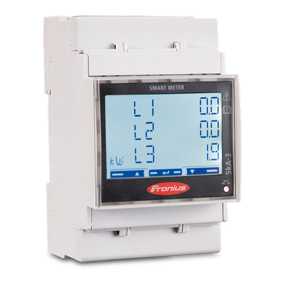
Fronius Smart Meter TS 5kA-3
42,0426,0348,EN 008-27112020
Fronius prints on elemental chlorine free paper (ECF) sourced from certified sustainable forests (FSC).
Operating instructions
PV system monitoring
Advertisement
Table of Contents

Related Manuals for Fronius TS 5kA-3


Summary of Contents for Fronius TS 5kA-3
- Page 1 / Perfect Charging / Perfect Welding / Solar Energy LEARN MORE WITH OUR HOW-TO VIDEOS www.youtube.com/FroniusSolar Operating instructions Fronius Smart Meter TS 5kA-3 PV system monitoring 42,0426,0348,EN 008-27112020 Fronius prints on elemental chlorine free paper (ECF) sourced from certified sustainable forests (FSC).
-
Page 3: Table Of Contents
Setting the address on the Fronius Smart Meter TS Start-up Fronius SnapINverter General Connecting to the Fronius Datamanager Configuring the Fronius Smart Meter TS as the primary meter Configuring the Fronius Smart Meter TS as a secondary meter Fronius GEN24 inverter General Installation using the web browser... -
Page 5: Safety Rules
Safety rules... -
Page 7: Safety Rules
Safety rules Explanation of DANGER! safety notices Indicates immediate danger. ▶ If not avoided, death or serious injury will result. WARNING! Indicates a potentially hazardous situation. ▶ If not avoided, death or serious injury may result. CAUTION! Indicates a situation where damage or injury could occur. ▶... -
Page 8: Environmental Conditions
For the location of the safety and danger notices on the device, refer to the section headed "General remarks" in the Operating Instructions for the device. Any equipment malfunctions which might impair safety must be remedied before the device is turned on. This is for your personal safety! Environmental Operation or storage of the device outside the stipulated area will be deemed as not in... -
Page 9: General Information
General information... -
Page 11: Fronius Smart Meter
Fronius Smart Meter TS 5kA-3 Device descrip- The Fronius Smart Meter TS is a bidirectional electricity meter which optimises self-con- tion sumption and records the household's load curve. In conjunction with the Fronius inverter, Fronius Datamanager and Fronius data interface, the Fronius Smart Meter TS provides a clear overview of a user's own power consumption. -
Page 12: Information On The Device
Dangerous electrical voltage. Intended use The Fronius Smart Meter TS is a fixed piece of equipment for public grids of TN/TT sys- tems and records self-consumption and/or individual loads in the system. The Fronius Smart Meter TS is required for systems with a battery storage system and/or a Fronius... -
Page 13: Scope Of Supply
The Fronius Smart Meter TS must only be operated in accordance with the specifications in the enclosed documentation and in accordance with local laws, reg- ulations, provisions, standards and within the limits of technical possibilities. -
Page 14: Measuring Accuracy
26. Measuring accur- The Fronius Smart Meter TS has accuracy class 1 when measuring active energy (EN IEC 62053-21) in the voltage ranges 400 - 480 VLL or 230 -277 VLN. Within the voltage ranges 173 - 400 VLL or 100 - 230 VLN the accuracy class is 2 (active energy according to EN IEC 62053-21, reactive energy according to EN IEC 62053-23). -
Page 15: Installation
Installation... -
Page 17: Installation
Setting the transformation ratio of the current and voltage transformers on page 29). If several Fronius Smart Meter TS are installed in the system, set the address (see "Setting the address" under Setting the address on the Fronius Smart Meter TS on page 30). -
Page 18: Installation
(circuit breaker, switch or disconnector) and overcurrent‑protection (automatic‑circuit breaker). The Fronius Smart Meter TS consumes 10 - 30 mA, the nominal capacity of the discon- necting devices and the overcurrent‑protection is determined by the wire thickness, the mains voltage and the required breaking capacity. -
Page 19: Cabling
Cabling IMPORTANT! Always switch off the power supply before connecting the mains voltage inputs to the Fronius Smart Meter TS. Recommended thickness of stranded mains voltage cables for the terminals of the measuring input and measuring output: Wire: 1 - 4 mm²... - Page 20 2 phases, 3 conductors (VT/CT connection) 3 phases, 3 conductors (CT connection) 3 phases, 3 conductors (VT/CT connection) 3 phases, 4 conductors (Aron CT connection)
-
Page 21: Selection Criteria For Current Transformer
The Fronius Smart Meter TS needs 0.5 VA to carry out its measurements. Losses also occur on the outgoing and return leads. The power of the current converter must be greater than the sum total of the power of the Fronius Smart Meter TS and the leads. The higher the power, the better. -
Page 22: Connecting The Current Transformers
2.2 VA Example The length of the outgoing and return lead (0.5 m each) between the Fronius Smart Meter TS and the current transformer is a total of 1 m and has a copper cable cross-sec- tion of 1.5 mm²; the line resistance is therefore 0.6 VA according to the table above. The self-consumption of the Fronius Smart Meter TS is 0.5 VA. -
Page 23: Terminating Resistors - Explanation Of Symbols
Two wires can be installed in each terminal; the wires are twisted first, inserted into the terminal and tightened. Note: A loose wire can disable an entire area of the network. ▶ The data communication connections of the Fronius Smart Meter TS are electrically isolated from hazardous voltages. Terminating res- Inverter in the system istors - Explana- e. -
Page 24: Connecting The Terminating Resistor
Connecting the The terminating resistor is integrated in the terminating res- Fronius Smart Meter TS and is manufac- istor tured with a bridge between the M and T connections (T = termination). Terminating res- Due to interference, it is recommended that terminating resistors are used as illustrated istors below to ensure proper functioning. -
Page 25: Mounting The Connection Cover
* The terminating resistor is integrated in the Fronius Smart Meter TS and is manufac- tured with a bridge between the M and T connections (T = termination). Mounting the Insert the connection covers into the connection cover guides and press firmly. -
Page 26: Multi-Meter System - Explanation Of Symbols
Terminating resistor R 120 Ohm Multi-meter sys- If several Fronius Smart Meter TS are installed, a separate address must be set for each (see Setting the address on the Fronius Smart Meter TS on page 30). The primary... -
Page 27: Menu Structure And Parameters
2 to 14. Different Fronius Smart Meter power categories can be used in combination. IMPORTANT! Max. Use 3 secondary meters in the system. Location of the primary meter in the consumption branch. *Terminating resistor R 120 Ohm Location of the primary meter at the feed-in point. - Page 28 Screen Code Description Values SYStEM Type of system 3Pn*: three-phase system, 4- core 3P: three-phase system, 3- core 2P: two-phase system, 3-core Ct rAtIo Current transformer ratio from 1* to 1000 Ut rAtIo Voltage transformer ratio from 1* to 1000 MEASurE Measurement mode ** A: easy connection, measures...
-
Page 29: Setting The Transformation Ratio Of The Current And Voltage Transformers
1), 3) Ratio of voltage transformers (001.0 - 1000 Important! Changing the transformation ratios will reset the counters in the Fronius Smart Meter TS to 0. Transformation ratio in the current transformer x Transformation ratio of the voltage transformers = max. 1000... -
Page 30: Setting The Address On The Fronius Smart Meter Ts
Setting the Symbol Name Event Function address on the Scroll one screen forward, increase the value Fronius Smart by 1 Meter TS Down Scroll one screen back, decrease the value by Enter Call up settings, confirm value 2 seconds Press and hold "Enter" for 2 seconds. -
Page 31: Start-Up
Start-up... -
Page 33: Fronius Snapinverter
The service password must be entered in order to access the "Meter" menu item. Three-phase or single-phase Fronius Smart Meter TS can be used. In both cases, the selection is made under the "Fronius Smart Meter" item. The Fronius Datamanager auto- matically identifies the meter type. -
Page 34: Configuring The Fronius Smart Meter Ts As A Secondary Meter
Enter the name of the secondary meter in the "Name" input field. Enter the previously assigned address in the “Modbus address” input field. Add meter description. Click the button to save the settings. The Fronius Smart Meter TS is configured as a secondary meter. -
Page 35: Fronius Gen24 Inverter
The service password must be entered in order to access the "System configuration" menu item. Three-phase or single-phase Fronius Smart Meter TS can be used. In both cases, the selection is made under the "Components" menu area. The meter type is determined automatically. -
Page 36: Configuring The Fronius Smart Meter Ts As The Primary Meter
Access the "Components“ menu area. Click the "Add component" button. In the "Position" drop-down list, set the position of the meter (feed-in point or con- sumption point). For more information on the position of the Fronius Smart Meter TS, Positioning on page 13. -
Page 37: Technical Data
Technical data Technical data Modbus transmission speed: 9600 baud Parity bit:none Software version: Fronius Datamanager 2.0 (from version 3.16.1 onwards) Fronius Symo Hybrid (from version 1.16.1 onwards) Measuring input Three-phase nominal voltage 400 - 480 V (-20% to +15%) Operating range 400 - 173 VLL ±... - Page 38 Energy Response time after switch-on < 5 s (EN IEC 62053-21, EN IEC 62053-23) kCT x kVT Maximum display Resolution 1 - 9.9 9 9 9 9 9 9 . 9 9 kWh / kvarh 10 Wh / varh 10 - 99.9 9 9 9 9 9 9 9 .
-
Page 39: Fronius Manufacturer's Warranty
0.05 mm² Recommended torque max. 0.4 Nm Fronius manufac- Detailed, country-specific warranty terms are available on the internet: turer's warranty www.fronius.com/solar/warranty To obtain the full warranty period for your newly installed Fronius inverter or storage sys- tem, please register at: www.solarweb.com. - Page 40 FRONIUS INTERNATIONAL GMBH Froniusstraße 1 A-4643 Pettenbach AUSTRIA contact@fronius.com www.fronius.com Under www.fronius.com/contact you will find the addresses of all Fronius Sales & Service Partners and locations.
Need help?
Do you have a question about the TS 5kA-3 and is the answer not in the manual?
Questions and answers