Table of Contents

Related Manuals for Technosoft iPOS360X MX-CAN


Summary of Contents for Technosoft iPOS360X MX-CAN
- Page 1 MX-CAN Intelligent Servo Drive for Step, DC, Brushless DC and AC Motors Intelligent Servo Drives Technical Reference © Technosoft 2023 P091.028.iPOS360X.MX.CAN.UM.0723 © Technosoft 2023 iPOS360x MX-CAN Technical Reference...
-
Page 2: Table Of Contents
Motherboard PCB Design ..................13 EMC recommendations....................14 Connectors and Pinouts .................... 15 3.5.1 Pinouts for iPOS360X MX-CAN ..................... 15 ..3.5.2 Mating Connectors for iPOS360X MX-CAN ................15 ..Connection diagrams ....................16 3.6.1 iPOS360X MX-CAN connection diagram ................16 ..3.6.2 24V Digital I/O Connection .................... -
Page 3: Read This First
Whilst Technosoft believes that the information and guidance given in this manual is correct, all parties must rely upon their own skill and judgment when making use of it. Technosoft does not assume any liability to anyone for any loss or damage caused by any error or omission in the work, whether such error or omission is the result of negligence or any other cause. -
Page 4: About This Manual
In order to operate the iPOS360X drives, you need to pass through 3 steps: ❑ Step 1 Hardware installation ❑ Step 2 Drive setup using Technosoft EasySetUp software for drive commissioning ❑ Step 3 Motion programming using one of the options: ❑... -
Page 5: Related Documentation
TML motion programming and motion evaluation tools. Help of the EasySetUp software – describes how to use EasySetUp to quickly setup any Technosoft drive for your application using only 2 dialogues. The output of EasySetUp is a set of setup data that can be downloaded into the drive EEPROM or saved on a PC file. -
Page 6: If You Need Assistance
DISCONNECT WIRES FROM THE DRIVE WHILE THE POWER SUPPLIES ARE ON WARNING! THE DRIVE MAY HAVE HOT SURFACES DURING OPERATION. DURING DRIVE OPERATION, THE CONTROLLED MOTOR WILL MOVE. KEEP WARNING! AWAY FROM ALL MOVING PARTS TO AVOID INJURY © Technosoft 2023 iPOS360x MX-CAN Technical Reference... -
Page 7: Cautions
Quality Austria Certificate about the application and further development of an effective Quality Management System complying with the requirements of Standard ISO 9001:2015 REACH Compliance - TECHNOSOFT hereby confirms that this product comply with the legal obligations regarding Article 33 of the European REACH Regulation 1907/2006 (Registration, Evaluation, Authorization and Restriction of Chemicals), which came into force on 01.06.2007. -
Page 8: Product Overview
PLC functionality in a single compact unit and are capable to execute complex motions without requiring intervention of an external motion controller. Using the high-level Technosoft Motion Language (TML) the following operations can be executed directly at drive level: ❑... -
Page 9: Product Features
Hence neither the iPOS360X TML programming capability nor the drive camming mode are used. EasySetUp can be downloaded free of charge from Technosoft web page. EasyMotion Studio platform includes EasySetUp for the drive setup, and a Motion Wizard for the motion programming. -
Page 10: Identification Labels
Two CAN operation modes selectable by HW pin (only for CAN drives): CANopen – conforming with CiA 301 v4.2 and CiA DSP 402_2 v4.1 • • TMLCAN – intelligent drive conforming with Technosoft protocol for exchanging TML commands via CAN-bus • 2K 16 internal SRAM memory for data acquisition •... -
Page 11: Supported Motor-Sensor Configurations
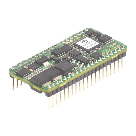
A circuit board is available for evaluating the iPOS3602 or 3604 MX CAN. It comes with multiple types of connectors for easy access to the iPOS360x features. Figure 2.5.1. iPOS360X MX-CAN mounted on the I/O iPOS360X extension board 2.5.1 Starter Kit ordering information... -
Page 12: Hardware Installation
Hardware Installation iPOS360X MX-CAN Board Dimensions Figure 3.1.1. iPOS360X MX-CAN drive dimensions All dimensions are in mm. The drawings are not to scale. Remark: The six pins located at the end of J1 are not installed in the standard configuration of the iPOS360x MX drive. -
Page 13: Motherboard Pcb Design
CONTENT IS ACCIDENTALLY CORRUPTED. THE iPOS360X IS AN ELECTROSTATICALLY SENSITIVE DEVICE, WHICH WILL BE DAMAGED BY INCORRECT HANDLING. THEREFORE CAUTION! THE DRIVE SHALL BE REMOVED FROM ITS ORIGINAL PACKAGE ONLY IN AN ESD PROTECTED ENVIRONMENT! © Technosoft 2023 iPOS360x MX-CAN Technical Reference... -
Page 14: Emc Recommendations
* if +Vmot to capacitor wire length ≥ 2m, use twisted wires for the supply and ground return (Vmot and GND) * if +Vmot to capacitor wire length ≥ 20m, the capacitor value must be ≥ 2200 µF. © Technosoft 2023 iPOS360x MX-CAN Technical Reference... -
Page 15: Connectors And Pinouts
Connectors and Pinouts 3.5.1 Pinouts for iPOS360X MX-CAN 3.5.2 Mating Connectors for iPOS360X MX-CAN Producer Part Number Image On-board connector Mating connector Fischer Elektronik SL 11 112 020 G BL 5 20 J1, J2 Standard socket for square pin 0.635 x 0.635 mm;... -
Page 16: Connection Diagrams
Connection diagrams 3.6.1 iPOS360X MX-CAN connection diagram Figure 3.3. iPOS360X MX-CAN Connection diagram * For other available feedback / motor options, check the detailed connection diagrams below © Technosoft 2023 iPOS360x MX-CAN Technical Reference... -
Page 17: Digital I/O Connection
The outputs are compatible with NPN type inputs (load is tied to common +V , output pulls to GND when active and is floating when inactive) The maximum sink current is 0.5A continuous, up to 1A pulsed for less than 5 seconds © Technosoft 2023 iPOS360x MX-CAN Technical Reference... -
Page 18: Digital I/O Connection
The output loads can be individually and independently connected to +5V or to GND. The length of the cables must be up to 30m, reducing the exposure to voltage surges in industrial environment. © Technosoft 2023 iPOS360x MX-CAN Technical Reference... -
Page 19: Analog Inputs Connection
(GND); shield is connected only at the drive side, to the drive GND, and is left unconnected at the source side. The source minus (negative, out-of-phase) output remains unconnected. © Technosoft 2023 iPOS360x MX-CAN Technical Reference... -
Page 20: Motor Connections
Brushless Motor connection Figure 3.8. Brushless motor connection 3.6.5.2 2-phase Step Motor connection Figure 3.9. 2-phase step motor connection, one coil per phase Figure 3.10. 2-phase step motor connection, two coils per phase © Technosoft 2023 iPOS360x MX-CAN Technical Reference... -
Page 21: 3-Phase Step Motor Connection
The inductors must be magnetically shielded (toroidal, for example), and must be rated for the motor surge current. Typically the necessary values are around 100 μH. A good shielding can be obtained if the motor wires are running inside a metallic cable guide. © Technosoft 2023 iPOS360x MX-CAN Technical Reference... -
Page 22: Feedback Connections
For the encoder differential connection, external 120Ω (0.25W) terminators are required for long encoder cables, or noisy environments. The length of the cables must be up to 30m, reducing the exposure to voltage surges in industrial environment. © Technosoft 2023 iPOS360x MX-CAN Technical Reference... -
Page 23: Digital Hall Connection For Motor + Hall + Incremental Encoder
Do not connect unterminated wires. They might pick up unwanted noise and give false encoder readings. The length of the cables must be up to 30m, reducing the exposure to voltage surges in industrial environment. © Technosoft 2023 iPOS360x MX-CAN Technical Reference... -
Page 24: Linear Hall Connection
If the iPOS360x 5V supply output is used by another device (like for example an encoder) and the connection cable is longer than 5 meters, add a decoupling capacitor near the supplied device, between the +5V and GND lines. The capacitor value can be 1...10 μF, rated at 6.3V © Technosoft 2023 iPOS360x MX-CAN Technical Reference... -
Page 25: Power Supply Connection
= 38V is the over-voltage protection limit is the nominal motor supply voltage = the overall energy flowing back to the supply in Joules. In case of a rotary motor and load, E can be computed with the formula: © Technosoft 2023 iPOS360x MX-CAN Technical Reference... - Page 26 CHOP where C is the capacitance on the motor supply (external), i.e: CHOP to limit the average current below the drive nominal current I =2A for iPOS3602 and 4A for iPOS3604 © Technosoft 2023 iPOS360x MX-CAN Technical Reference...
-
Page 27: Serial Rs-232 Connection
Do not rely on an earthed PC to provide the iPOS360X GND connection! The drive must be earthed through a separate circuit. Most communication problems are caused by the lack of such connection © Technosoft 2023 iPOS360x MX-CAN Technical Reference... -
Page 28: Can-Bus Connection (For Can Drives Only)
For 1 Mbit/s (worst case), the maximum stub length must be below 0.3 meters. The 120 termination resistors must be rated at 0.2W minimum. Do not use winded resistors, which are inductive. Figure 3.22. Multiple-Axis CAN network © Technosoft 2023 iPOS360x MX-CAN Technical Reference... -
Page 29: Disable Of Autorun Mode (For Can) / Disable Setup (For Cat)
Operation Mode and Axis ID Selection for CAN drives The iPOS360x MX-CAN drives have 3 dedicated pins which choose the CAN operation mode and hardware Axis ID value. These pins are sampled at drive power up. The drive works correctly when the logic supply is powered with a minimum of 7V. - Page 30 0 to 6 (0 for L0, 1 for L1, 2 for L2, etc.) If the resulting AxisID value is 0, the axis ID will be set to 255 Figure 3.24. Axis ID Setting Examples. CANopen mode © Technosoft 2023 iPOS360x MX-CAN Technical Reference...
- Page 31 Figure 3.25. Axis ID Setting Examples. TMLCAN mode © Technosoft 2023 iPOS360x MX-CAN Technical Reference...
-
Page 32: Axis Id Settings For Can Drives And Canopen Mode
Axis ID Settings for CAN drives and CANopen mode Axis Axis Axis Axis Axis Axis Axis Axis Axis ID 2 ID 1 ID 0 CANopen ID 2 ID 1 ID 0 CANopen ID 2 ID 1 ID 0 CANopen © Technosoft 2023 iPOS360x MX-CAN Technical Reference... -
Page 33: Axis Id Settings For Can Drives And Tmlcan Mode
L4 L6 L3 L5 L6 L3 L3 L6 L4 L4 L6 L4 L5 L6 L4 L3 L6 L5 L4 L6 L5 L5 L6 L5 L3 L6 L6 L4 L6 L6 L5 L6 L6 © Technosoft 2023 iPOS360x MX-CAN Technical Reference... -
Page 34: Electrical Specifications
= 12V Supply current = 24V = 40V iPOS360x can be operated in vacuum (no altitude restriction), but at altitudes over 2,500m, current and power rating are reduced due to thermal dissipation efficiency. © Technosoft 2023 iPOS360x MX-CAN Technical Reference... -
Page 35: Motor Supply Input
Logic “HIGH”; Internal 4.7K pull-up to +3.3 Logic “HIGH”; Pulled to +5V Input current 0.15 Logic “HIGH”; Pulled to +24V Input frequency Minimum pulse width µs ESD protection Human body model ±2 3.8.9 Digital Outputs (OUT0, OUT2/Error, OUT3/ Ready) © Technosoft 2023 iPOS360x MX-CAN Technical Reference... -
Page 36: Digital Hall Inputs (Hall1, Hall2, Hall3)
Offset error Assuming parameter RFOFFSET=0 ±4 ±24 bits Gain error Assuming parameter RFGAIN=0x7EB8 (32440) ±1.5% ±4% % FS Bandwidth (-3dB) Software selectable ESD protection Human body model ±2 “FS” stands for “Full Scale” © Technosoft 2023 iPOS360x MX-CAN Technical Reference... -
Page 37: Encoder Inputs (A+, A-, B+, B-, Z+, Z-)
Encoder differential input pins do not have internal 120Ω termination resistors connected across For full RS-422 compliance, 120Ω termination resistors must be connected across the differential pairs, as close as possible to the drive input pins. See Figure 3.14. Differential incremental encoder connection © Technosoft 2023 iPOS360x MX-CAN Technical Reference... - Page 38 KHZ, CORRELATE THE PWM FREQUENCY WITH THE MOTOR PARAMETERS IN ORDER TO AVOID POSSIBLE MOTOR 10 11 DAMAGE. Current [A] Figure 3.34. iPOS3604 MX Over-current diagram – the output voltage, V – the motor supply voltage © Technosoft 2023 iPOS360x MX-CAN Technical Reference...
-
Page 39: Memory Map
4000h ROM memory for: TML programs Cam tables Setup information 4FFFh 5000h Reserved 5FFFh Data acquisitions 9800h cam tables at runtime SRAM memory TML Programs 9FCFh Figure 4.1. iPOS360X MX Memory Map © Technosoft 2023 iPOS360x MX-CAN Technical Reference...
Need help?
Do you have a question about the iPOS360X MX-CAN and is the answer not in the manual?
Questions and answers