
Subscribe to Our Youtube Channel
Related Manuals for Pilz PSSu E F PS-P


Summary of Contents for Pilz PSSu E F PS-P
- Page 1 PSSu E F PS-P(-T)(-R) Decentralised system PSSuniversal I/O Operating Manual-21286-EN-07...
- Page 2 Preface This document is a translation of the original document. All rights to this documentation are reserved by Pilz GmbH & Co. KG. Copies may be made for internal purposes. Suggestions and comments for improving this documentation will be gratefully received.
-
Page 3: Table Of Contents
General wiring guidelines 6.1.1 Mechanical connection of the base modules Terminal configuration Connecting the module Section 7 Operation Messages Display elements 7.2.1 Anzeigeelemente zur Moduldiagnose 7.2.2 Display elements for the status of the periphery supply Operating Manual PSSu E F PS-P(-T)(-R) 21286-EN-07... - Page 4 Contents Section 8 Technical details Section 9 Order reference Product Accessories Operating Manual PSSu E F PS-P(-T)(-R) 21286-EN-07...
-
Page 5: Introduction
Introduction Validity of documentation This documentation is valid for the product types PSSu E F PS-P, PSSu E F PS-P-T and PSSu E F PS-P-R. It is valid until new documentation is published. The module PSSu E F PS-P-T is suitable for use where there are increased environmental requirements (see Technical Details). - Page 6 Introduction INFORMATION This gives advice on applications and provides information on special fea- tures. Operating Manual PSSu E F PS-P(-T)(-R) 21286-EN-07...
-
Page 7: Overview
Infeed for C-rail supply LEDs for: – Periphery supply – Module error Application range depends on the base module T-type: PSSu E F PS-P-T: for increased environmental requirements R-type: PSSu E F PS-P-R: for railway applications Operating Manual PSSu E F PS-P(-T)(-R) 21286-EN-07... -
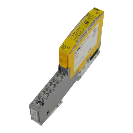
Page 8: Front View
2D code 3: Labelling strip for the terminal configuration on the base module 4: Name of electronic module 5: Connection level 1 6: Connection level 2 7: Connection level 3 8: Connection level 4 Operating Manual PSSu E F PS-P(-T)(-R) 21286-EN-07... - Page 9 10: Round connection holes (connection levels 1, 2, 3 and 4) for connecting the signal lines 11: Mounting slot for colour marker to label the connection level (connection levels 1, 2, 3 and 4) Operating Manual PSSu E F PS-P(-T)(-R) 21286-EN-07...
-
Page 10: Safety
The PSSu E F PS-P module may be used in conjunction with the following base modules: PSSu BS 1/8 S PSSu BS 1/8 C The PSSu E F PS-P-T and PSSu E F PS-P-R modules may be used in conjunction with the following base modules: PSSu BS 1/8 S-T... -
Page 11: Safety Regulations
In safety-related applications, please comply with the mission time T in the safety-re- lated characteristic data. When decommissioning, please comply with local regulations regarding the disposal of electronic devices (e.g. Electrical and Electronic Equipment Act). Operating Manual PSSu E F PS-P(-T)(-R) 21286-EN-07... -
Page 12: Function Description
Details"). If the current load is higher, an additional supply voltage module is required to re- fresh the periphery supply. Periphery supply The current load is the total current consumption of the sensors, actuators and test pulses supplied via the input/output modules. Operating Manual PSSu E F PS-P(-T)(-R) 21286-EN-07... - Page 13 If the current load is higher, the C-rail must use a different supply to prevent overload. Please refer to the derating diagram. PSSu E F PS-P: Derating diagram for periphery supply and C-rail: Temperature T depend- ent on load current I T (°C)
-
Page 14: Integrated Protection Mechanisms
I/O-Group (SafetyBUS p) is set to zero. The I/O-Group switches to a STOP condition. An error telegram is then triggered on Safety- BUS p and the error is entered in the PSSuniversal error stack. Operating Manual PSSu E F PS-P(-T)(-R) 21286-EN-07... -
Page 15: Installation
5.1.1 Dimensions Base modules with four connection levels: 12,6 mm 8,1 mm 52,1 mm (0.496") (0.319") (2.051") 12,6 mm 72,6 mm (0.496") (2.858") Operating Manual PSSu E F PS-P(-T)(-R) 21286-EN-07... -
Page 16: Installing The Base Module
Push the base module back [2] until you hear it lock into position. On the mounting rail, slide the base module to the left until you hear the two lateral mounting hooks on the adjacent module lock into position [3]. Schematic representation: Operating Manual PSSu E F PS-P(-T)(-R) 21286-EN-07... -
Page 17: Inserting And Removing An Electronic Module
This is how the base module is coded. The mechanics of the electronic modules are designed for 50 plug in/out cycles. Operating Manual PSSu E F PS-P(-T)(-R) 21286-EN-07... -
Page 18: Inserting An Electronic Module
Installation 5.3.1 Inserting an electronic module Procedure: The electronic module must audibly lock into position [1]. Mark the electronic module using the labelling strips [2]. Schematic representation: Operating Manual PSSu E F PS-P(-T)(-R) 21286-EN-07... -
Page 19: Removing An Electronic Module
– The substitute values are used for the modules' FS outputs, with Valid Bits = FALSE. CAUTION! Sparking can cause interference and errors! Only change the module when the load is switched off! Operating Manual PSSu E F PS-P(-T)(-R) 21286-EN-07... -
Page 20: Wiring
Insert the stripped cable into the round fixing hole [2], as far as it will go. – Tighten up the screw on the screw terminal. – Check that the cable is firmly seated. Operating Manual PSSu E F PS-P(-T)(-R) 21286-EN-07... - Page 21 Inputs/outputs on the counter modules: 1.5 mm (AWG16) – Analogue inputs/outputs: 1.5 mm (AWG16) – Communication cables: 1.5 mm (AWG16) – Test pulse outputs: 1.5 mm (AWG16) – Power supply: 2.5 mm (AWG12) – Functional earth: 2.5 mm (AWG12) Operating Manual PSSu E F PS-P(-T)(-R) 21286-EN-07...
-
Page 22: Terminal Configuration
(12-22 linked within the base module) 13 -23: +24 V periphery sup- ply, interrupted to the left (13-23 linked within the base module) 14-24 C-rail supply, interrupted to the left (14-24 linked within the base module) Operating Manual PSSu E F PS-P(-T)(-R) 21286-EN-07... - Page 23 Module bus Module Supply [ . . . ] (24 V DC) 24 V DC 24 V DC Refreshing of Periphery Supply Periphery Supply (24 V DC) (24 V DC) C-rail Supply C-rail Supply Operating Manual PSSu E F PS-P(-T)(-R) 21286-EN-07...
-
Page 24: Connecting The Module
PSSu E F PS-P/ PSSu E F PS-P-T with - PSSu BS 1/8S(-T) - PSSu BS 1/8C(-T) C-rail Supply Connect to the 0 V supply and earth at a single point Periphery Supply Operating Manual PSSu E F PS-P(-T)(-R) 21286-EN-07... -
Page 25: Operation
Display elements Legend LED on LED off 7.2.1 Anzeigeelemente zur Moduldiagnose The module has an LED for displaying module errors ("Err" LED). Meaning Name Colour Status - - - No error Module error Operating Manual PSSu E F PS-P(-T)(-R) 21286-EN-07... -
Page 26: Display Elements For The Status Of The Periphery Supply
A status LED is assigned to the periphery supply (“24 V” LED). Description Colour Status 24 V - - - No supply voltage or er- ror in the sup- ply voltage for periphery sup- green Supply voltage for periphery supply is er- ror-free Operating Manual PSSu E F PS-P(-T)(-R) 21286-EN-07... - Page 27 5 mA 5 mA 5 mA Module's power con- sumption with no load 0,12 W 0,12 W 0,12 W Max. power dissipation of module 0,5 W 0,5 W 0,5 W Operating Manual PSSu E F PS-P(-T)(-R) 21286-EN-07...
- Page 28 Vibration In accordance with the standard EN 60068-2-6 EN 60068-2-6 EN 50125-3 Frequency 10 - 150 Hz 10 - 1000 Hz 5 - 2000 Hz Amplitude 0,35 mm 0,35 mm – 0,23g Acceleration Operating Manual PSSu E F PS-P(-T)(-R) 21286-EN-07...
- Page 29 76 mm 76 mm 76 mm Width 12,6 mm 12,6 mm 12,6 mm Depth 60,2 mm 60,2 mm 60,2 mm 33 g 34 g 35 g Weight Mechanical coding Type Colour Yellow Yellow Yellow Operating Manual PSSu E F PS-P(-T)(-R) 21286-EN-07...
- Page 30 Technical details Where standards are undated, the 2015-03 latest editions shall apply. Operating Manual PSSu E F PS-P(-T)(-R) 21286-EN-07...
- Page 31 Base module with cage clamp terminals, for use only as the first 312 651 module after the head module PSSu BS 1/8 C-T Base module with cage clamp terminals, for use only as the first 314 651 module after the head module, T-type Operating Manual PSSu E F PS-P(-T)(-R) 21286-EN-07...
- Page 32 Front cover Support Technical support is available from Pilz round the clock. Americas Australia Scandinavia Brazil +61 3 95600621 +45 74436332 +55 11 97569-2804 Spain Canada Europe +34 938497433 +1 888-315-PILZ (315-7459) Austria Switzerland +41 62 88979-30 Mexico +43 1 7986263-0...
Need help?
Do you have a question about the PSSu E F PS-P and is the answer not in the manual?
Questions and answers