
Subscribe to Our Youtube Channel
Related Manuals for Pilz PSSu E F INC


Summary of Contents for Pilz PSSu E F INC
- Page 1 PSSu E F INC(-T) Decentralised system PSSuniversal I/O Operating Manual-1001454-EN-09...
- Page 2 Preface This document is a translation of the original document. All rights to this documentation are reserved by Pilz GmbH & Co. KG. Copies may be made for internal purposes. Suggestions and comments for improving this documentation will be gratefully received.
-
Page 3: Table Of Contents
Installing the base module Inserting and removing an electronic module 5.3.1 Inserting an electronic module 5.3.2 Removing an electronic module 5.3.3 Changing an electronic module during operation Section 6 Wiring General wiring guidelines Operating Manual PSSu E F INC(-T) 1001454-EN-09... - Page 4 Display elements for module diagnostics 7.2.2 Display elements for counter status 7.2.3 Display elements for status of the functional inputs Status information Section 8 Technical Details Safety characteristic data Section 9 Order reference Product Accessories Operating Manual PSSu E F INC(-T) 1001454-EN-09...
-
Page 5: Operating Manual Pssu E F Inc(-T)
Introduction Validity of documentation This documentation is valid for the products PSSu E F INC and PSSu E F INC-T. It is valid until new documentation is published. This operating manual explains the function and operation, describes the installation and provides guidelines on how to connect the product. -
Page 6: Definition Of Symbols
It also highlights areas within the text that are of particular import- ance. INFORMATION This gives advice on applications and provides information on special fea- tures. Operating Manual PSSu E F INC(-T) 1001454-EN-09... -
Page 7: Overview
Data transfer per input A, B, C – Status per functional input (Gate, Latch, Status) – Module error For failsafe applications in system environment B (automation system PSS 4000) T-type: PSSu E F INC-T: for increased environmental requirements Operating Manual PSSu E F INC(-T) 1001454-EN-09... -
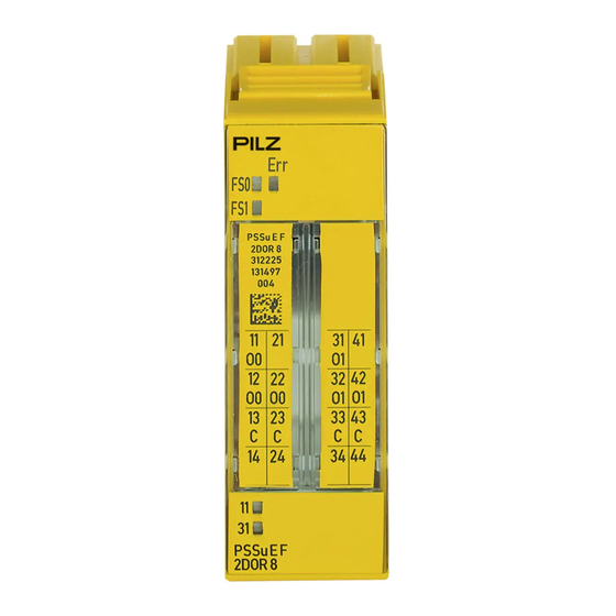
Page 8: Front View
Hardware version number – 2D code 3: Labelling strip for the terminal configuration on the base module 4: LEDs for – Status of function inputs G, L, S 5: Name of electronic module Operating Manual PSSu E F INC(-T) 1001454-EN-09... - Page 9 11: Round connection holes (connection levels 1, 2, 3 and 4) for connecting the signal lines 12: Mounting slot for colour marker to label the connection level (connection levels 1, 2, 3 and 4) Operating Manual PSSu E F INC(-T) 1001454-EN-09...
-
Page 10: Safety
The module may be used for failsafe applications in system environment B (automation system PSS 4000). The modules PSSu E F INC and PSSu E F INC-T may be used as a safety components in accordance with the Lifts Directive 95/16/EC in accordance with the requirements of EN 81-1/2:1998+A3:2009, EN 81-20:2015, EN 81-50:2015, EN 81-22:2014 and... - Page 11 The module is supported by PAS4000 from Version 1.1.1. We recommend that you always use the latest version (download from www.pilz.de). The PSSu E F INC module may be used in conjunction with the following base modules: PSSu BP 2/16 S...
-
Page 12: Safety Regulations
In safety-related applications, please comply with the mission time T in the safety-re- lated characteristic data. When decommissioning, please comply with local regulations regarding the disposal of electronic devices (e.g. Electrical and Electronic Equipment Act). Operating Manual PSSu E F INC(-T) 1001454-EN-09... -
Page 13: Function Description
3 single-pole inputs referenced to earth: G, L, S, for special functions Operating modes Incremental encoder Counter Functions Period length measurement Storing the counter status in latch memory after a latch pulse or zero pulse Operating Manual PSSu E F INC(-T) 1001454-EN-09... -
Page 14: Functional Inputs (G, L, S)
5555 0000 is exceeded (the lower third of the value range). The status information underflow is reset: if FFFF FFFF is exceeded again (overflow). if AAAA FFFF is exceeded (the upper third of the value range). Operating Manual PSSu E F INC(-T) 1001454-EN-09... -
Page 15: Incremental Encoder Operating Mode
The module has received a latch pulse. Provided the function is activated, the counter value is copied into the latch memory with a rising edge at input L. e: The counter is disabled because there is a 1 signal at input G. Operating Manual PSSu E F INC(-T) 1001454-EN-09... -
Page 16: Counter Operating Mode
The module has received a latch pulse. Provided the function is activated, the counter value is copied into the latch memory with a rising edge at input L. e: The counter is disabled because there is a 1 signal at input G. Operating Manual PSSu E F INC(-T) 1001454-EN-09... -
Page 17: Functions
FFFF FFFF The module issues the result of period length measurement in multiples of 200 ns. Example: The process image of inputs contains 32 The period length is 200 ns x 50 = 10 μs Operating Manual PSSu E F INC(-T) 1001454-EN-09... -
Page 18: Transfer Counter Status Via Latch Pulse
FFFF FFFF The module always transmits the counter status when the first latch pulse occurs after the function has started. All subsequent latch pulses are ignored until the function is completed and reset. Operating Manual PSSu E F INC(-T) 1001454-EN-09... -
Page 19: Transfer Counter Status Via Zero Pulse
The module always transmits the counter status when the first zero pulse occurs after the function has started. The counter statuses on all subsequent zero pulses are ignored until the function has been completed and reset. Operating Manual PSSu E F INC(-T) 1001454-EN-09... -
Page 20: Set Counter Status
In the user program, set OutputData.Set- Counter Acknowledge transfer The module sets InputData.SetCounter- Done; InputData.Underflow and Input- Data.Overflow are reset Finish transfer In the user program, reset OutputData.Set- Counter Ready for new function The module resets InputData.SetCounter- Done Operating Manual PSSu E F INC(-T) 1001454-EN-09... -
Page 21: Configuration
TRUE: Input L (latch pulse) active/ period length measurement active SetCounter: BOOL FALSE: Do not transfer default counter status TRUE: Transfer default counter status NewCounterValue: Default counter status DWORD Operating Manual PSSu E F INC(-T) 1001454-EN-09... - Page 22 Transmitting the status via two bits enables simple fault detection: Two redundant bits must always be the same, two diverse bits must always be different, otherwise the transmission is faulty. Operating Manual PSSu E F INC(-T) 1001454-EN-09...
-
Page 23: Installation
For mechanical reasons it is not possible to mix base modules with screw terminals and base modules with cage clamp terminals. All contacts should be protected from contamination. The mechanics of the base modules are designed for 50 plug in/out cycles. Operating Manual PSSu E F INC(-T) 1001454-EN-09... -
Page 24: Inserting And Removing An Electronic Module
This is how the base module is coded. The mechanics of the electronic modules are designed for 50 plug in/out cycles. Operating Manual PSSu E F INC(-T) 1001454-EN-09... -
Page 25: Inserting An Electronic Module
Installation 5.3.1 Inserting an electronic module Procedure: The electronic module must audibly lock into position [1]. Mark the electronic module using the labelling strips [2]. Schematic representation: Operating Manual PSSu E F INC(-T) 1001454-EN-09... -
Page 26: Removing An Electronic Module
– The substitute values are used for the modules' FS outputs, with Valid Bits = FALSE. CAUTION! Sparking can cause interference and errors! Only change the module when the load is switched off! Operating Manual PSSu E F INC(-T) 1001454-EN-09... -
Page 27: Mechanical Connection Of The Base Modules
The terminal configuration as stated in the technical documentation applies for all other base modules. 6.1.1 Mechanical connection of the base modules Procedure: Use a flat blade screwdriver (DIN 5264-A)! DIN 5264-A Operating Manual PSSu E F INC(-T) 1001454-EN-09... - Page 28 The minimum cable cross section for field connection terminals on the base modules is 0.14 mm (AWG26). The maximum cable cross section for field connection terminals is: – Digital inputs: 1.5 mm (AWG16) – Digital outputs: 2.0 mm (AWG14) – Inputs/outputs on the counter modules: 1.5 mm (AWG16) Operating Manual PSSu E F INC(-T) 1001454-EN-09...
- Page 29 To crimp the ferrules you can use crimp pliers (crimp form A or C) conforming to EN 60947-1, such as the PZ 1.5 or PZ 6.5 from Weidmüller, for example. – Maximum torque setting: 0.8 Nm Use copper wiring. Operating Manual PSSu E F INC(-T) 1001454-EN-09...
-
Page 30: Terminal Configuration
32-42: Input S (Status) (32-42 linked within the base module) 13-23-33-43: Shield connec- tion (13-23, 33-43 linked within the base module) 14: Input A- 24: Input B- 34: Input C- 44: Input L (Latch) Operating Manual PSSu E F INC(-T) 1001454-EN-09... - Page 31 32-42: Input S (Status) (32-42 linked within the base module) 13-23-33-43: C-rail supply shield connection (13-23, 33-43 linked within the base module) 14: Input A- 24: Input B- 34: Input C- 44: Input L (Latch) Operating Manual PSSu E F INC(-T) 1001454-EN-09...
-
Page 32: Connecting The Module
Connecting the module Incremental encoder operating mode With C-rail Encoder supply via the PSSu E PD mod- Gate Status Latch Incremental encoder operating mode Without C-rail Encoder supply via the PSSu E PD mod- Gate Status Latch Operating Manual PSSu E F INC(-T) 1001454-EN-09... - Page 33 S) not connected. A+ (Count) B+ (Up/Down) C+ (Gate) Counter operating mode Without C-rail Encoder supply via the PSSu E PD mod- Function inputs (G, L, S) not connected. A+ (Count) B+ (Up/Down) C+ (Gate) Operating Manual PSSu E F INC(-T) 1001454-EN-09...
- Page 34 Wiring INFORMATION To achieve the safety values PL e and SIL CL 3 , 2 counter modules must be used: a PSSu E F INC and a PSSu E F ABS SSI. Operating Manual PSSu E F INC(-T) 1001454-EN-09...
-
Page 35: Operation
Legend LED on LED off 7.2.1 Display elements for module diagnostics The module has an LED for displaying module errors ("Err" LED). Meaning Name Colour Status - - - No error Module error Operating Manual PSSu E F INC(-T) 1001454-EN-09... -
Page 36: Display Elements For Counter Status
0 signal at function input S Green 1 signal at function input S Status information The I/O data with status information is described in the chapter entitled "Function Descrip- tion", under "Input/output data". Operating Manual PSSu E F INC(-T) 1001454-EN-09... -
Page 37: Technical Details
Max. number of bits on the counter input 32 Bit 32 Bit Evaluation of counter pulses Phase offset between differential signals A and B 90 deg 90 deg Phase offset tolerance 30 deg 30 deg Operating Manual PSSu E F INC(-T) 1001454-EN-09... - Page 38 10 - 150 Hz 10 - 1000 Hz 0,35 mm 0,35 mm Amplitude Acceleration Broadband noise EN 60068-2-64 In accordance with the standard – Frequency – 5 - 500 Hz Acceleration – 1,9grms Operating Manual PSSu E F INC(-T) 1001454-EN-09...
- Page 39 76 mm Height Width 25,2 mm 25,4 mm Depth 60,2 mm 60,2 mm Weight 49 g 51 g Mechanical coding Type Colour Yellow Yellow Where standards are undated, the 2005-04 latest editions shall apply. Operating Manual PSSu E F INC(-T) 1001454-EN-09...
-
Page 40: Safety Characteristic Data
A safety function's SIL/PL values are not identical to the SIL/PL values of the units that are used and may be different. We recommend that you use the PAScal software tool to calculate the safety function's SIL/PL values. Operating Manual PSSu E F INC(-T) 1001454-EN-09... -
Page 41: Order Reference
Base module with C-rail and screw terminals, T-type 314 630 PSSu BP-C 2/16 C Base module with C-rail and cage clamp terminals 312 631 PSSu BP-C 2/16 C-T Base module with C-rail and cage clamp terminals, T-type 314 631 Operating Manual PSSu E F INC(-T) 1001454-EN-09... - Page 42 Front cover Support Technical support is available from Pilz round the clock. Americas Australia Scandinavia Brazil +61 3 95600621 +45 74436332 +55 11 97569-2804 Spain Canada Europe +34 938497433 +1 888-315-PILZ (315-7459) Austria Switzerland +41 62 88979-30 Mexico +43 1 7986263-0...
Need help?
Do you have a question about the PSSu E F INC and is the answer not in the manual?
Questions and answers