GORMAN-RUPP PUMPS 10 Series Installation, Operation, And Maintenance Manual With Parts List
Hide thumbs
Also See for 10 Series:

Related Manuals for GORMAN-RUPP PUMPS 10 Series


Summary of Contents for GORMAN-RUPP PUMPS 10 Series
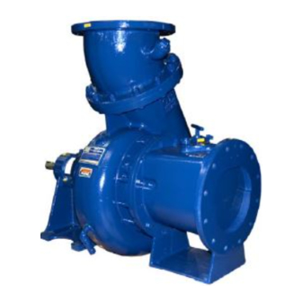
- Page 1 OM‐06717-01 January 8, 2015 INSTALLATION, OPERATION, AND MAINTENANCE MANUAL WITH PARTS LIST 10 SERIES PUMP MODEL 14C2-QSF2.8P FT4 GORMAN‐RUPP PUMPS www.grpumps.com 2015 Gorman‐Rupp Pumps Printed in U.S.A.
- Page 2 Register your new Gorman‐Rupp pump online at www.grpumps.com Valid serial number and e‐mail address required. The engine exhaust from this product contains chemicals known to the State of California to cause cancer, birth defects or other reproductive harm. RECORD YOUR PUMP MODEL AND SERIAL NUMBER Please record your pump model and serial number in the spaces provided below.
-
Page 3: Table Of Contents
TABLE OF CONTENTS INTRODUCTION ........... PAGE I - 1 SAFETY - SECTION A . - Page 4 TABLE OF CONTENTS (continued) STOPPING ..............PAGE C - 3 Manual Stopping .
-
Page 5: Introduction
10 SERIES OM-06717 INTRODUCTION Thank You for purchasing a Gorman‐Rupp pump. HAZARD AND INSTRUCTION Read this manual carefully to learn how to safely DEFINITIONS install and operate your pump. Failure to do so could result in personal injury or damage to the The following are used to alert maintenance per... -
Page 6: Safety - Section A
10 SERIES OM-06717 SAFETY - SECTION A This information applies to 10 Series en pump or endanger personnel as a result of pump failure. gine driven pumps. Refer to the manual accompanying the engine before at tempting to begin operation. - Page 7 10 SERIES OM-06717 heated pump. Vapor pressure within the pump can cause parts being disen gaged to be ejected with great force. Al low the pump to cool before servicing. Fuel used by internal combustion en gines presents an extreme explosion and fire hazard.
-
Page 8: Installation - Section B
10 SERIES OM-06717 INSTALLATION - SECTION B Review all SAFETY information in Section A. to the pump is critical to performance and safety, be sure to limit the incoming pressure to 50% of Since pump installations are seldom identical, this... -
Page 9: Battery Specifications And Installation
OM-06717 10 SERIES c. Carefully read all warnings and cautions con POSITIONING PUMP tained in this manual or affixed to the pump, and perform all duties indicated. Lifting d. Check levels and lubricate as necessary. Re fer to LUBRICATION in the MAINTENANCE AND REPAIR section of this manual and per... -
Page 10: Clearance
10 SERIES OM-06717 only; however, the engine manufacturer should be to secure them when filled with liquid and under consulted for continuous operation at angles pressure. greater than 15 Gauges Clearance Most pumps are drilled and tapped for installing discharge pressure and vacuum suction gauges. If... -
Page 11: Sealing
OM-06717 10 SERIES Sealing of the suction pipe. The baffle will allow entrained air to escape from the liquid before it is drawn into Since even a slight leak will affect priming, head, the suction inlet. and capacity, especially when operating with a... -
Page 12: Discharge Lines
10 SERIES OM-06717 In low discharge head applications (less than 30 DISCHARGE LINES feet (9,1 m)), it is recommended that the bypass line be run back to the wet well, and located 6 Siphoning inches below the water level or cut‐off point of the low level pump. -
Page 13: Automatic Air Release Valve
OM-06717 10 SERIES Figures 4 and 5 show a cross‐sectional view of the Automatic Air Release Valve, and a corresponding description of operation. During the priming cycle, air from the pump casing flows through the bypass A manual shut‐off valve should not be line, and passes through the Air Release Valve to installed in any bypass line. -
Page 14: Air Release Valve Installation
10 SERIES OM-06717 ny for information about an Automatic Air Release connected to the discharge line of the self‐priming Valve for your specific application. centrifugal pump (see Figure 6). NOTE Air Release Valve Installation If the Air Release Valve is to be installed on a staged pump application, contact the factory for specific installation instructions. -
Page 15: Operation - Section C
OM-06717 10 SERIES OPERATION - SECTION C OPERATION Review all SAFETY information in Section A. Make sure the pump is level. Lower jack Follow the instructions on all tags, labels and stands and chock the wheels, if so decals attached to the pump. -
Page 16: Routine Operation
OM-06717 10 SERIES Add liquid to the pump casing when: continuous operating speed for this pump. 1. The pump is being put into service for the first time. A Gorman‐Rupp automatic air release valve may 2. The pump has not been used for a consider... -
Page 17: Operation In Extreme Heat
OM-06717 10 SERIES before servicing it. Approach any over‐heated OPERATION IN EXTREME HEAT pump cautiously. The safety shutdown system will automatically stop the unit if engine operating temperature ex ceeds design limits. If engine over‐temperature shutdown occurs, allow the unit to cool before re... - Page 18 OM-06717 10 SERIES Automatic Stopping Bearing Temperature Check Bearings normally run at higher than ambient tem In the automatic mode, the pump will stop when peratures because of heat generated by friction. the liquid in the wet well or sump lowers and acti...
- Page 19 OM-06717 10 SERIES for approximately one minute; this will remove any large solids from clogging the drain port and pre remaining liquid that could freeze the pump rotat venting the pump from completely draining, insert ing parts. If the pump will be idle for more than a a rod or stiff wire in the drain port, and agitate the few hours, or if it has been pumping liquids con...
- Page 20 10 SERIES OM-06717 TROUBLESHOOTING - SECTION D Review all SAFETY information in Section A. to ensure that the pump will remain inoperative. 3. Allow the pump to completely cool if overheated. 4. Check the temperature before opening any covers, plates, or Before attempting to open or service the plugs.
- Page 21 OM-06717 10 SERIES Table 1. Trouble Shooting Chart (cont.) TROUBLE POSSIBLE CAUSE PROBABLE REMEDY PUMP STOPS OR FAILS Leaking or worn seal or pump gas Check pump vacuum. Replace ket. leaking or worn seal or gasket. TO DELIVER RATED FLOW OR PRESSURE Strainer clogged.
- Page 22 10 SERIES OM-06717 Table 1. Trouble Shooting Chart (cont.) TROUBLE POSSIBLE CAUSE PROBABLE REMEDY BEARINGS RUN TOO Bearing temperature is high, but Check bearing temperature regular within limits. ly to monitor any increase. Low or incorrect lubricant. Check for proper type and level of lubricant.
- Page 23 OM-06717 10 SERIES Preventive Maintenance Schedule Service Interval* Item Daily Weekly Monthly Semi‐ Annually Annually General Condition (Temperature, Unusual Noises or Vibrations, Cracks, Leaks, Loose Hardware, Etc.) Pump Performance (Gauges, Speed, Flow) Bearing Lubrication Seal Lubrication (And Packing Adjustment, If So Equipped) V‐Belts (If So Equipped)
- Page 24 OM-06717 10 SERIES PUMP MAINTENANCE AND REPAIR - SECTION E MAINTENANCE AND REPAIR OF THE WEARING PARTS OF THE PUMP WILL MAINTAIN PEAK OPERATING PERFORMANCE. STANDARD PERFORMANCE FOR PUMP MODEL 14C2‐QSF2.8P FT4 Based on 70 F (21 C) clear water at sea level Contact the Gorman‐Rupp Company to verify part...
- Page 25 OM-06717 10 SERIES PARTS PAGE ILLUSTRATION Figure 1. Pump Model 14C2‐QSF2.8P FT4 PAGE E - 2 MAINTENANCE & REPAIR...
- Page 26 OM-06717 10 SERIES PARTS LIST Pump Model 14C2‐QSF2.8P FT4 (From S/N 1639613 Up) If your pump serial number is followed by an “N”, your pump is NOT a standard production model. Contact the Gorman‐Rupp Company to verify part numbers. ITEM...
- Page 27 OM-06717 10 SERIES ILLUSTRATION Figure 2. Power Unit Kit PAGE E - 4 MAINTENANCE & REPAIR...
- Page 28 OM-06717 10 SERIES PARTS LIST Power Unit Kit ITEM PART NAME PART ITEM PART NAME PART NUMBER NUMBER BASE/FUEL TANK ASSY 41553-029 24150 HOSE BARB FITTING 26523-447 QSF2.8P FT4 ENGINE 29216-401 AIR VENT S1703 CONT PANEL INST KIT 48122-553 LOCKING FUEL CAP...
- Page 29 OM-06717 10 SERIES ILLUSTRATION Figure 3. Pump End Assembly PAGE E - 6 MAINTENANCE & REPAIR...
- Page 30 OM-06717 10 SERIES PARTS LIST Pump End Assembly ITEM PART NAME PART ITEM PART NAME PART NUMBER NUMBER PUMP CASING SEE NOTE BELOW BALL BEARING S1096 IMPELLER 9934A 11060 IMPELLER SHAFT 38514-809 16040 STUD C0606 15991 GREASE SEAL ASSY. GS1250...
- Page 31 OM-06717 10 SERIES ILLUSTRATION Figure 4. Drive Assembly PARTS LIST ITEM PART PART NAME NUMBER COUPLING KIT 48112-001 -BUSHING 24131-345 -COUPLING ASSEMBLY 44165-011 -LOCK WASHER J06 15991 -LOCK WASHER 21171-536 -SOCKET HD CAP SCREW BD0606-1/2 15991 -SOCKET HD CAP SCREW...
- Page 32 OM-06717 10 SERIES PUMP AND SEAL DISASSEMBLY AND REASSEMBLY Review all SAFETY information in Section A. Before attempting to open or service the pump: Follow the instructions on all tags, label and de 1. Familiarize yourself with this man cals attached to the pump.
- Page 33 OM-06717 10 SERIES may be serviced by removing the back cover as casing until fully engaged. Support the pump us sembly (45). ing a suitable hoist and the lifting eye. Remove the cover clamp screw (43) and clamp bar Remove the hardware (6 and 7) securing the inter...
- Page 34 OM-06717 10 SERIES shaft (34) with the “V” notch positioned over the Remove the nuts (26) securing the pump casing to shaft key. the intermediate (20). Use the hoist and sling to separate the intermediate and rotating portion of With the impeller rotation still blocked, see Figure 5 the pump from the pump casing.
- Page 35 OM-06717 10 SERIES Inspect the seal liner (55) for wear or grooves strongly recommended that the bearings which could cause leakage or damage to the seal be replaced any time the shaft and bear packing rings. The seal liner is a press fit in the seal ings are removed.
- Page 36 OM-06717 10 SERIES small nicks and burrs with a fine file or emery cloth. Replace the shaft if defective. Position the inboard oil seal (27) in the intermediate When installing the bearings onto the housing bore with the lip positioned as shown in shaft, never press or hit against the outer Figure 3.
- Page 37 OM-06717 10 SERIES ly positioned on the shaft. The heads of the caps lubricant such as vegetable oil or glycerin, or a sili crews in the center of the coupling must be posi con‐based lubricant such as “WD40” or equivalent.
- Page 38 OM-06717 10 SERIES To ease installation of the seal, lubricate the pack oil on the finished faces. Assemble the seal as fol ing rings and seal liner with water or a very small lows, (see Figure 6). amount of oil, and apply a drop of light lubricating...
- Page 39 OM-06717 10 SERIES chamfered side toward the shaft shoulder and ing to the intermediate with the nuts (26). Do not slide it onto the shaft until fully seated. fully tighten the nuts until the impeller face clear ance has been set.
- Page 40 OM-06717 10 SERIES NOTE Final Pump Assembly If the suction flange was removed, replace the gas (Figure 1) ket (51) and apply `Permatex Aviation No. 3 Form‐A‐ Gasket' or equivalent compound to the mating sur Install any leveling shims used under the pump faces.
- Page 41 OM-06717 10 SERIES POSITION POSITION POSITION WHEN WHEN EMPTY FILLING IN USE GREASE FITTING CROSS RELIEF HOLE NOTE: When installing a new grease cup, lubricate the cup as indicated on the installation tag furnished with the grease cup. Figure . Automatic Lubricating Grease Cup...
- Page 42 For Warranty Information, Please Visit www.grpumps.com/warranty or call: U.S.: 419-755-1280 Canada: 519-631-2870 International: +1-419-755-1352 GORMAN‐RUPP PUMPS...
Need help?
Do you have a question about the 10 Series and is the answer not in the manual?
Questions and answers