
Related Manuals for GORMAN-RUPP PUMPS 12D-1B30 FT4


Summary of Contents for GORMAN-RUPP PUMPS 12D-1B30 FT4
- Page 1 OM-07219-01 December 11, 2018 INSTALLATION, OPERATION, AND MAINTENANCE MANUAL WITH PARTS LIST 10 SERIES PUMP MODEL 12D-1B30 FT4 GORMAN‐RUPP PUMPS www.grpumps.com 2018 Gorman‐Rupp Pumps Printed in U.S.A.
- Page 2 Register your new Gorman‐Rupp pump online at www.grpumps.com Valid serial number and e‐mail address required. The engine exhaust from this product contains chemicals known to the State of California to cause cancer, birth defects or other reproductive harm. RECORD YOUR PUMP MODEL AND SERIAL NUMBER Please record your pump model and serial number in the spaces provided below.
-
Page 3: Table Of Contents
TABLE OF CONTENTS INTRODUCTION ..........PAGE I - 1 SAFETY ‐... - Page 4 TABLE OF CONTENTS (continued) Pump Parts Only ............PAGE E - 5 PUMP AND SEAL DISASSEMBLY AND REASSEMBLY .
-
Page 5: Introduction
10 SERIES OM-07219 INTRODUCTION Thank You for purchasing a Gorman‐Rupp pump. HAZARD AND INSTRUCTION Read this manual carefully to learn how to safely DEFINITIONS install and operate your pump. Failure to do so could result in personal injury or damage to the The following are used to alert maintenance per... -
Page 6: Safety - Section A
10 SERIES OM-07219 SAFETY ‐ SECTION A This information applies to 10 Series en damage the pump or endanger person gine driven pumps. Refer to the manual nel as a result of pump failure. accompanying the engine before at tempting to begin operation. Because pump installations are seldom After the pump has been installed, make identical, this manual cannot possibly... - Page 7 OM-07219 10 SERIES 5. Vent the pump slowly and cau tiously. 6. Refer to instructions in this manual before restarting the pump. Never tamper with the governor to gain more power. The governor establishes safe operating limits that should not be exceeded.
-
Page 8: Installation - Section B
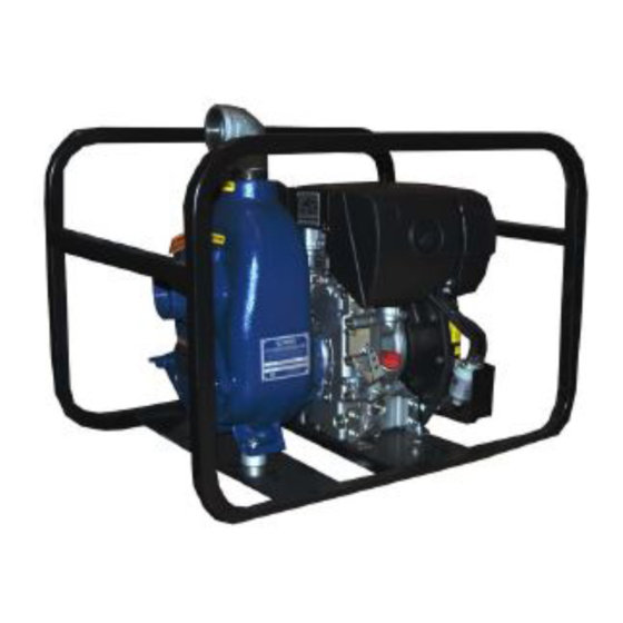
[ 15,9 ] 20.00 13.50 [ 508,0] [ 342,9] 21.00 28.00 [ 533,4] [ 711,2 ] 21.50 DIMENSIONS: [ 546,1] INCHES POWERED BY HATZ 1B30 FT4 DIESEL ENGINE APPROX [MILLIMETERS] Figure 1. Pump Model 12D-1B30 FT4 INSTALLATION PAGE B - 1... -
Page 9: Preinstallation Inspection
OM-07219 10 SERIES or piping before attempting to lift existing, installed PREINSTALLATION INSPECTION units. The pump assembly was inspected and tested be Mounting fore shipment from the factory. Before installation, inspect the pump for damage which may have oc Locate the pump in an accessible place as close as curred during shipment. -
Page 10: Line Configuration
10 SERIES OM-07219 Line Configuration Fittings Suction lines should be the same size as the pump Keep suction and discharge lines as straight as inlet. If reducers are used in suction lines, they possible to minimize friction losses. Make mini should be the eccentric type, and should be in... -
Page 11: Suction Line Positioning
OM-07219 10 SERIES If it is necessary to position inflow close to the suc Suction Line Positioning tion inlet, install a baffle between the inflow and the The depth of submergence of the suction line is suction inlet at a distance 1‐1/2 times the diameter critical to efficient pump operation. -
Page 12: Bypass Lines
10 SERIES OM-07219 stalled in the discharge line to protect the pump Bypass Lines from excessive shock pressure and reverse rota If a system check valve is used due to high dis tion when it is stopped. charge head, it may be necessary to vent trapped air from the top of the pump during the priming process. -
Page 13: Operation - Section C
OM-07219 10 SERIES OPERATION - SECTION C Review all SAFETY information in Section A. not prime when dry. Extended operation of a dry pump will destroy the seal assembly. Follow the instructions on all tags, labels and Add liquid to the pump casing when: decals attached to the pump. -
Page 14: Lines With A Bypass
OM-07219 10 SERIES Lines With a Bypass pump and allow it to cool before servicing it. Refill the pump casing with cool liquid. Close the discharge throttling valve (if so equipped) so that the pump will not have to prime against the weight of the liquid in the discharge line. -
Page 15: Stopping
OM-07219 10 SERIES After stopping the pump, remove the positive bat STOPPING tery cable to ensure that the pump will remain inop erative. Never halt the flow of liquid suddenly. If the liquid being pumped is stopped abruptly, damaging Cold Weather Preservation shock waves can be transmitted to the pump and piping system. -
Page 16: Troubleshooting - Section D
10 SERIES OM-07219 TROUBLESHOOTING - SECTION D Review all SAFETY information in Section A. Before attempting to open or service the pump: 1. Familiarize yourself with this manual. 2. Shut down the engine and take pre cautions to ensure that the pump will remain inoperative. - Page 17 OM-07219 10 SERIES TROUBLE POSSIBLE CAUSE PROBABLE REMEDY PUMP STOPS OR Air leak in suction line. Correct leak. FAILS TO DELIVER Suction intake not submerged at Check installation and correct RATED FLOW OR proper level or sump too small. submergence as needed. PRESSURE Lining of suction hose collapsed.
-
Page 18: Preventive Maintenance
10 SERIES OM-07219 equipped) between regularly scheduled inspec PREVENTIVE MAINTENANCE tions can indicate problems that can be corrected Since pump applications are seldom identical, and before system damage or catastrophic failure oc pump wear is directly affected by such things as curs. -
Page 19: Pump Maintenance And Repair - Section E
PUMP MAINTENANCE AND REPAIR ‐ SECTION E MAINTENANCE AND REPAIR OF THE WEARING PARTS OF THE PUMP WILL MAINTAIN PEAK OPERATING PERFORMANCE. STANDARD PERFORMANCE FOR PUMP MODEL 12D-1B30 FT4 Based on 70 F (21 C) clear water at sea level formance or part numbers. - Page 20 OM-07219 10 SERIES ILLUSTRATION PARTS PAGE 15 13 16 Figure 1. Pump Model 12D-1B30 FT4 PAGE E - 2 MAINTENANCE & REPAIR...
-
Page 21: Parts Lists
10 SERIES OM-07219 PARTS LIST Pump Model 12D-1B30 FT4 (From S/N 1685933 Up) If your pump serial number is followed by an “N”, your pump is NOT a standard production model. Contact the Gorman‐Rupp Company to verify part numbers. ITEM... - Page 22 OM-07219 10 SERIES ILLUSTRATION Figure 2. Pump Parts Only PAGE E - 4 MAINTENANCE & REPAIR...
- Page 23 10 SERIES OM-07219 PARTS LIST Pump Parts Only ITEM PART PART NAME NUMBER PUMP CASING SEE NOTE BELOW FILL PLUG ASSY 48271-063 STREET ELBOW RS32 11999 GREASE CUP STREET ELBOW AGS04 11999 HEX HD CAPSCREW 22645-135 LOCK WASHER 21171-510 INTERMEDIATE ASSY 2935 10010 HEX NUT D06 15991...
- Page 24 OM-07219 10 SERIES PUMP AND SEAL DISASSEMBLY AND REASSEMBLY Before attempting to open or service the Review all SAFETY information in Section A. pump: 1. Familiarize yourself with this man ual. Follow the instructions on all tags, labels and 2. Shut down the engine and remove decals attached to the pump.
- Page 25 10 SERIES OM-07219 To service the suction check valve, remove the suc Impeller Removal tion piping. Remove the hex nuts (9) securing the (Figure 2) suction flange (25) to the pump casing (1). Pull the check valve assembly (26) from the suction port. Before removing the impeller (12), turn the cross arm on the automatic grease cup (4) clockwise un...
- Page 26 OM-07219 10 SERIES Disassembly, and position it on the bed of an ar The seal is not normally reused because wear pat bor (or hydraulic) press. Use a new sleeve to force terns on the finished faces cannot be realigned the old one out.
- Page 27 10 SERIES OM-07219 SPRING SEAL INTERMEDIATE LINER IMPELLER SHIMS PACKING RINGS SPACER SLEEVE SHAFT STATIONARY ELEMENTS IMPELLER ROTATING ROTATING ELEMENT ELEMENT STATIONARY WASHERS Figure 3. Seal Assembly Install the outboard rotating element with the chamfered side toward the impeller end of the shaft.
- Page 28 OM-07219 10 SERIES Pump Casing Installation Install the washers (22). Secure the back cover as sembly by tightening the wing nuts (23) evenly. Do (Figure 2) not over tighten the wing nuts; they should be just tight enough to ensure a good seal at the back cov Install the same thickness of pump casing gaskets er shoulder.
- Page 29 10 SERIES OM-07219 this will release the spring to apply grease to the seal (see Figure 4). POSITION POSITION POSITION WHEN WHEN EMPTY FILLING IN USE GREASE FITTING CROSS RELIEF HOLE Figure 4. Automatic Lubricating Grease Cup Engine Consult the literature supplied with the engine, or contact your local engine representative.
- Page 30 For Warranty Information, Please Visit www.grpumps.com/warranty or call: U.S.: 419-755-1280 Canada: 519-631-2870 International: +1-419-755-1352 GORMAN‐RUPP PUMPS...
Need help?
Do you have a question about the 12D-1B30 FT4 and is the answer not in the manual?
Questions and answers