GORMAN-RUPP PUMPS 10 Series Installation, Operation And Maintenance Manual
Hide thumbs
Also See for 10 Series:

Related Manuals for GORMAN-RUPP PUMPS 10 Series


Summary of Contents for GORMAN-RUPP PUMPS 10 Series
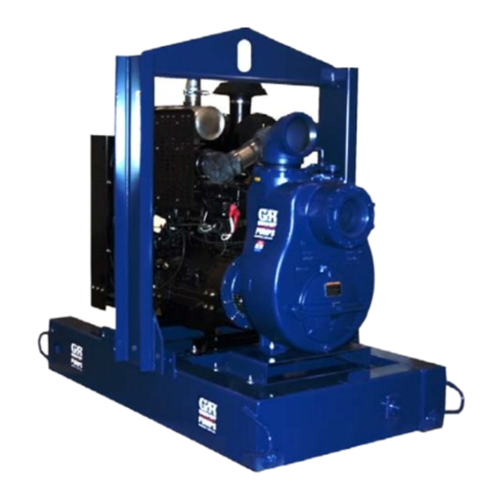
- Page 1 OM-06542-01 February 14, 2012 INSTALLATION, OPERATION, AND MAINTENANCE MANUAL WITH PARTS LIST 10 SERIES PUMP MODEL 16C20-4045T GORMAN‐RUPP PUMPS www.grpumps.com 2012 Gorman‐Rupp Pumps Printed in U.S.A.
- Page 2 Register your new Gorman‐Rupp pump online at www.grpumps.com Valid serial number and e‐mail address required. The engine exhaust from this product contains chemicals known to the State of California to cause cancer, birth defects or other reproductive harm. RECORD YOUR PUMP MODEL AND SERIAL NUMBER Please record your pump model and serial number in the spaces provided below.
-
Page 3: Table Of Contents
TABLE OF CONTENTS INTRODUCTION ..........PAGE I - 1 SAFETY - SECTION A . - Page 4 TABLE OF CONTENTS (continued) PUMP MAINTENANCE AND REPAIR - SECTION E ....PAGE E - 1 PERFORMANCE CURVE ........... PAGE E - 1 PARTS LISTS: PUMP MODEL ASSEMBLY...
-
Page 5: Introduction
10 SERIES OM-06542 INTRODUCTION Thank You for purchasing a Gorman‐Rupp pump. HAZARD AND INSTRUCTION Read this manual carefully to learn how to safely DEFINITIONS install and operate your pump. Failure to do so could result in personal injury or damage to the The following are used to alert maintenance per... -
Page 6: Safety - Section A
10 SERIES OM-06542 SAFETY - SECTION A This information applies to 10 Series en any liquids which may damage the gine driven pumps. Refer to the manual pump or endanger personnel as a result accompanying the engine before at of pump failure. - Page 7 10 SERIES OM-06542 pipe plugs, or fittings from an over Fuel used by internal combustion en heated pump. Vapor pressure within the gines presents an extreme explosion pump can cause parts being disen and fire hazard. Make certain that all gaged to be ejected with great force.
-
Page 8: Installation - Section B
10 SERIES OM-06542 INSTALLATION - SECTION B Review all SAFETY information in Section A. specific application. Since the pressure supplied to the pump is critical to performance and safety, Since pump installations are seldom identical, this be sure to limit the incoming pressure to 50% of... -
Page 9: Battery Specifications And Installation
OM-06542 10 SERIES c. Carefully read all tags, decals, and markings POSITIONING PUMP on the pump assembly, and follow the instruc tions indicated. d. Check levels and lubricate as necessary. Re fer to LUBRICATION in the MAINTENANCE Death or serious personal injury and AND REPAIR section of this manual and per... -
Page 10: Clearance
10 SERIES OM-06542 Clearance Gauges Most pumps are drilled and tapped for installing When positioning the pump, allow a minimum discharge pressure and vacuum suction gauges. If clearance of 18 inches (457 mm) in front of the these gauges are desired for pumps that are not... -
Page 11: Suction Lines In Sumps
OM-06542 10 SERIES high suction lift, all connections in the suction line air to escape from the liquid before it is drawn into should be sealed with pipe dope to ensure an air the suction inlet. tight seal. Follow the sealant manufacturer's rec... -
Page 12: Discharge Lines
10 SERIES OM-06542 DISCHARGE LINES In low discharge head applications (less than 30 feet (9,1 m)), it is recommended that the bypass line be run back to the wet well, and located 6 Siphoning inches below the water level or cut‐off point of the low level pump. -
Page 13: Automatic Air Release Valve
OM-06542 10 SERIES through the bypass line and then close automati cally when the pump is fully primed and pumping at full capacity. A manual shut‐off valve should not be installed in any bypass line. A manual shut‐off valve may inadvertently be left closed during operation. -
Page 14: Alignment
10 SERIES OM-06542 Connect the valve outlet to a bleed line which fold pipe. Contact your Gorman‐Rupp distributor or slopes back to the wet well or sump. The bleed line the Gorman‐Rupp Company for information about must be the same size as the outlet opening or installation of an Automatic Air Release Valve for larger, depending on which Air Release Valve is be... -
Page 15: Operation - Section C
OM-06542 10 SERIES OPERATION - SECTION C OPERATION Review all SAFETY information in Section A. Make sure the pump is level. Lower jack Follow the instructions on all tags, labels and stands and chock the wheels, if so decals attached to the pump. -
Page 16: Lines With A Bypass
OM-06542 10 SERIES Add liquid to the pump casing when: continuous operating speed for this pump. 1. The pump is being put into service for the first time. A Gorman‐Rupp automatic air release valve may 2. The pump has not been used for a consider... -
Page 17: Leakage
OM-06542 10 SERIES Liquid Temperature And Overheating The maximum liquid temperature for this pump is F (71 C). Do not apply it at a higher operating Do not operate the pump against a temperature. closed discharge throttling valve for Overheating can occur if operated with the valves long periods of time. - Page 18 OM-06542 10 SERIES shock waves can be transmitted to the pump and into service. Consult the factory for ad piping system. Close all connecting valves slowly. ditional information. PERIODIC CHECKS Stopping Seal Cavity and Bearing Lubrication Reduce the throttle speed slowly, and allow the en...
-
Page 19: Cold Weather Preservation
OM-06542 10 SERIES Consult the manual accompanying the engine, for approximately one minute; this will remove any and change the oil filter periodically as indicated. If remaining liquid that could freeze the pump rotat operated under extremely dusty conditions, ing parts. If the pump will be idle for more than a change the filter more frequently. -
Page 20: Troubleshooting - Section D
OM-06542 10 SERIES TROUBLESHOOTING - SECTION D Review all SAFETY information in Section A. Before attempting to open or service the pump: 1. Familiarize yourself with this manual. 2. Switch off the engine ignition and dis connect the positive battery cable to ensure that the pump will remain in... - Page 21 OM-06542 10 SERIES TROUBLE POSSIBLE CAUSE PROBABLE REMEDY PUMP STOPS OR Suction intake not submerged at Check installation and correct sub FAILS TO DELIVER proper level or sump too small. mergence as needed. RATED FLOW OR Impeller or other wearing parts worn Replace worn or damaged parts.
- Page 22 OM-06542 10 SERIES PREVENTIVE MAINTENANCE equipped) between regularly scheduled inspec tions can indicate problems that can be corrected Since pump applications are seldom identical, and before system damage or catastrophic failure oc pump wear is directly affected by such things as curs.
- Page 23 OM-06542 10 SERIES PUMP MAINTENANCE AND REPAIR - SECTION E MAINTENANCE AND REPAIR OF THE WEARING PARTS OF THE PUMP WILL MAINTAIN PEAK OPERATING PERFORMANCE. STANDARD PERFORMANCE FOR PUMP MODEL 16C20-4045T Based on 70 F (21 C) clear water at sea level Contact the Gorman‐Rupp Company to verify per...
- Page 24 OM-06542 10 SERIES PARTS PAGE ILLUSTRATION Figure 1. Pump Model 16C20-4045T PAGE E - 2 MAINTENANCE & REPAIR...
- Page 25 OM-06542 10 SERIES PARTS LIST Pump Model 16C20-4045T (From S/N 1586822 Up) If your pump serial number is followed by an “N”, your pump is NOT a standard production model. Contact the Gorman‐Rupp Company to verify part numbers. ITEM PART...
- Page 26 OM-06542 10 SERIES ILLUSTRATION Figure E-2. 46143-140 Power Unit Kit PAGE E - 4 MAINTENANCE & REPAIR...
- Page 27 OM-06542 10 SERIES PARTS LIST 46143-140 Power Unit Kit ITEM PART PART NAME NUMBER JOHN DEERE ENGINE 29224-411 BASE/FUEL TANK 41553-029 24150 LIFTING BAIL KIT 48274-803 MUFFLER GUARD ASSEMBLY 42331-061 MALE ELBOW 26351-131 CONNECTOR S1447 HOSE ASSEMBLY 46341-789 CONTROL PANEL...
- Page 28 OM-06542 10 SERIES ILLUSTRATION Figure 3. 16C20-(SAE 4/10) Pump End Assembly PAGE E - 6 MAINTENANCE & REPAIR...
- Page 29 OM-06542 10 SERIES PARTS LIST 16C20-(SAE 4/10) Pump End Assembly ITEM PART NAME PART ITEM PART NAME PART NUMBER NUMBER PUMP CASING SEE NOTE BELOW NAMEPLATE 38818-023 13990 BACK CVR PLATE ASSY 42111-935 DRIVE SCREW BM#04-03 17000 -PIPE PLUG P04 15079...
- Page 30 OM-06542 10 SERIES ILLUSTRATION Figure 4. 16C20-(SAE 4/10) Drive Assembly PARTS LIST ITEM PART PART NAME NUMBER COUPLING KIT 48112-001 -BUSHING 24131-345 -COUPLING ASSEMBLY 44165-011 SOCKET HD CAPSCREW BD0606-1/2 15991 SOCKET HD CAPSCREW 22644-220 LOCKWASHER J06 15991 LOCKWASHER 21171-536 HEX HD CAPSCREW...
- Page 31 OM-06542 10 SERIES PUMP AND SEAL DISASSEMBLY AND REASSEMBLY Before attempting to open or service the pump: Review all SAFETY information in Section A. 1. Familiarize yourself with this man ual. 2. Switch off the engine ignition and Follow the instructions on all tags, label and de...
- Page 32 OM-06542 10 SERIES Remove the cover clamp screw (17) and clamp bar (16) securing the back cover. Pull the back cover and assembled wear plate from the pump casing (1). Inspect the back cover gasket (13) and replace Do not attempt to lift the complete pump it if damaged or worn.
- Page 33 OM-06542 10 SERIES Reach through the suction port and wedge a block of wood between the vanes of the impeller and the pump casing to prevent rotation. Do not attempt to lift the complete pump If removed, install the shaft key (34) in the shaft unit using the lifting eye.
- Page 34 OM-06542 10 SERIES Inspect the oil seal (62) and if replacement is re be cleaned and inspected in place. It is quired, press it from the seal plate. strongly recommended that the bearings be replaced any time the shaft and bear...
- Page 35 OM-06542 10 SERIES small nicks and burrs with a fine file or emery cloth. hot plate may be used to heat the bearings. Bear Replace the shaft if defective. ings should never be heated with a direct flame or directly on a hot plate.
- Page 36 OM-06542 10 SERIES seated against the bore shoulder. Be careful not to flammable. Use them only in a well‐ven damage the lip of the oil seal (45A) on the shaft tilated area free from excessive heat, threads. sparks, and flame. Read and follow all precautions printed on solvent contain...
- Page 37 OM-06542 10 SERIES SEAL PLATE RETAINER AIR VENT SPRING SPRING HOLDER O‐RINGS IMPELLER SHAFT SLEEVE BOTTLE IMPELLER OILER SHAFT IMPELLER OIL SEAL SHIMS DRAIN PLUG BELLOWS STATIONARY SEAT DRIVE BAND STATIONARY ELEMENT ROTATING ELEMENT Figure 7. Seal Assembly The I.D. of the tube should be approximately the same as the I.D.
- Page 38 OM-06542 10 SERIES cover, by adding or removing gaskets in the pump casing gasket set (3) until the impeller scrapes against the wear plate when the shaft is turned by hand. After the impeller scrapes, add approximate The shaft and impeller threads must be ly .010 inch (0,25 mm) of gaskets.
- Page 39 OM-06542 10 SERIES Suction Check Valve Installation (Figure 3) Inspect the check valve assembly (27) and replace Make certain that the flexible portion of the it if badly worn. coupling is mounted as shown in Figure 4. This is critical. If the coupling is not prop...
- Page 40 OM-06542 10 SERIES surface which contacts the pump casing. This ac at the air vent (54) while filling. Check the oil level tion will reduce rust and scale build‐up. regularly and keep the bottle oiler full. Secure the back cover assembly by tightening the Bearings cover clamp screw (17) against the clamp bar (16).
- Page 41 For U.S. and International Warranty Information, Please Visit www.grpumps.com/warranty or call: U.S.: 419-755-1280 International: +1-419-755-1352 For Canadian Warranty Information, Please Visit www.grcanada.com/warranty or call: 519-631-2870 GORMAN‐RUPP PUMPS...
Need help?
Do you have a question about the 10 Series and is the answer not in the manual?
Questions and answers