GORMAN-RUPP PUMPS 10 Series Installation, Operation And Maintenance Manual
Hide thumbs
Also See for 10 Series:
Table of Contents
Advertisement
Quick Links
C
OM-00714-OB03
February 18, 1985
C June 23, 2023
Rev.
INSTALLATION, OPERATION,
AND MAINTENANCE MANUAL
WITH PARTS LIST
GORMAN-RUPP
10-SERIES PUMP
16A9-B
THE GORMAN-RUPP COMPANY • MANSFIELD, OHIO
GORMAN-RUPP OF CANADA LIMITED• ST. THOMAS, ONTARIO, CANADA
Pnnted lo U. S . A
©Copyright by the Gorman-Rupp Company
Advertisement
Table of Contents

Related Manuals for GORMAN-RUPP PUMPS 10 Series


Summary of Contents for GORMAN-RUPP PUMPS 10 Series
- Page 1 OM-00714-OB03 February 18, 1985 C June 23, 2023 Rev. INSTALLATION, OPERATION, AND MAINTENANCE MANUAL WITH PARTS LIST GORMAN-RUPP 10-SERIES PUMP 16A9-B THE GORMAN-RUPP COMPANY • MANSFIELD, OHIO GORMAN-RUPP OF CANADA LIMITED• ST. THOMAS, ONTARIO, CANADA Pnnted lo U. S . A ©Copyright by the Gorman-Rupp Company...
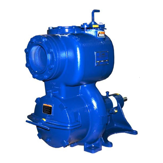
- Page 5 This Installation, Operation, and Maintenance Manual is designed to help you achieve the best performance and longest life from your Gorman-Rupp pump. This pump is a 10 Series, semi-open impeller, self-priming centrifugal model with a suction check valve. The pump is designed for handling corrosive liquids containing specified entrained solids, residues and slurries.
- Page 7 OH-00714 10 SERIES WARNINGS WARNINGS - SECTION A THESE WARNINGS APPLY TO 10 SERIES BASIC PUMPS. GORMAN-RUPP HAS NO CONTROL OVER OR PARTICULAR KNOWLEDGE OF THE POWER SOURCC REFER TO THE MANUAL ACCOMPANYING THE POWER WHICH WILL BE USED. SOURCE BEFORE ATTEMPTING TO BEGIN OPERATION.
- Page 8 10 SERIES OH-00714 WARNINGS WARNING !lll!/l!l//////l/!////I////////////II/I//I/II///IIIII///I/////I/ // Do not operate the pump without shields and/or guards in // place over the drive shafts, belts and/or couplings, or // other rotating parts. Exposed rotating parts can catch // // clothing, fingers, or tools, causing severe injury to personnel.
-
Page 9: Installation - Section B
10 SERIES OM-00714 INSTALLATION INSTALLATION - SECTION B Since pump installations are seldom identical, this section offers only general recommendations and practices required to inspect, position, and arrange the pump and piping. Most of the information pertains to a standard static lift application where the pump is positioned above the free level of liquid to be pumped. -
Page 10: Outline Drawing
10 SERIES otl-00714 INSTALLATION OUTLINE DRAWING � 1-- __w__ · ..ll.lL --f- ..JJI. 5 84 [IB .5I J2 Zi R E QU IRE D FOR i · - [3 311,2 1 1 3 2,1.1 1 51.11 REMO VAL DF BACK COVER PLATE moo""wi �,... -
Page 11: Positioning Pump
OM-00714 10 SERIES INSTALLATION on the pump. Check that the pump shaft rotates in the required direc tion. CAUTION Only operate this pump in the direction indicated by the arrow on the pump body and on the accompanying decal. Otherwise,... -
Page 12: Suction And Discharge Piping
OM-00714 10 SERIES INSTALLATION Clearance A minimum clearance of 18 inches in front of the cover plate is required to per mit removal of the cover and easy access to the pump interior. SUCTION AND DISCHARGE PIPING Materials Either pipe or hose may be used for suction and discharge lines; however, the materials must be compatible with the liquid being pumped. -
Page 13: Suction Lines
Or!-00714 10 SERIES INSTALLATION SUCTION LINES To avoid air pockets which could affect pump priming, the suction line must be as short and direct as possible. When operation involves a suction lift, the line must always slope upward to the pump from the source of the liquid being pumped;... -
Page 14: Discharge Lines
OM-00714 10 SERIES INSTALLATION NOTE The pipe submergence required may be reduced by installing a standard pipe increaser fitting at the end of the suction line. The larger opening size will reduce the inlet veloc ity. Calculate the required submergence using the follow... - Page 15 10 SERIES ml-00714 INSTALLATION Valves If a throttling valve is desired in the discharge line, use a valve as large as the largest pipe to minimize friction losses. Never install a throttling valve in a suction line. With high discharge heads, it is recommended that a throttling valve and a sys...
- Page 16 10 SERIES INSTALLATION NOTE ent of the Check Rotation, Section C, before final ali pump. When mounted at the Gorman-Rupp factory, driver and pump are aligned before shipment. Misalignment will occur in transit and handling. Pumps must be checked and realigned before operation.
- Page 17 10 SERIES OH-00714 INSTALLATION Figure 3A. Aligning Spider-Type Couplings Figure 38. Aligning Non-Spider Type Couplings Check parallel adjustment by laying a straightedge across both coupling rims at the top, bottom, and side. When the straightedge rests evenly on both halves of the coupling, the coupling is in horizontal parallel alignment.
- Page 18 10 SERIES m!-00714 INSTALLATION Tighten the belts in accordance with the belt manufacturer's instructions. the belts are too loose, they will slip; if the belts are too tight, there will be excessive power loss and possible bearing failure. Select pulleys that will match the proper speed ratio;...
-
Page 21: Operation
OM-00714 10 SERIES OPERATION OPERATION - SECTION C WARNING IIIIIIIIIIIIIIIIIIIIIIIIIIIIIIIIIIIIIIIIIIIIIIIIIIIIII/IIIIIIIII This pump is designed to pump corrosive liquids contain- specified entrained solids, residues and slurries. attempt pump volatile or flammable liquids which may damage the pump or endanger personnel as a re- sult of pump failure. - Page 22 OH-00714 10 SERIES OPERATION To fill the pump, remove the pump casing fill cover or fill plug at the top of the casing and add clean liquid until the pump is filled. Replace the fill cover or fill plug before operating the pump.
- Page 23 After the pump has primed and liquid is flowing steadily from the bypass line, open the discharge throttling valve. Orl-00714 10 SERIES OPERATION Lines Without a Bypass Open all valves in the discharge line and start the power source. Priming is in...
- Page 24 10 SERIES Orl-00714 OPERATION Strainer Check If a suction strainer has been shipped with the pump or installed by the user, check the strainer regularly, and clean it as necessary. The strainer should also be checked if pump flow rate begins to drop. If a vacuum suction gauge ha�...
-
Page 25: Bearing Temperature Check
OH-00714 10 SERIES OPERATION imately one minute; this will remove any remaining liquid that could freeze the pump rotating parts. If the pump will be idle for more than a few hours, or if it has been pumping liquids containing a large amount of solids, drain the pump, and flush it thor... -
Page 27: Troubleshooting
011-00714 .LU i::l.t..KJ..t.::t TROUBLESHOOTING PUMP TROUBLESHOOTING - SECTION D WARNING IIIIIIIIIIIIIIIIIIIIIIIIIIIIIIIIIIIIIIIIIIIIIIIIIIIIIIIIIIIIIIII Before attempting to open or service the pump: Familiarize yourself with this manual. Disconnect or lock out the power source to ensure that the pump will remain inoperative. Allow the pump to cool if overheated. Vent the pump slowly and cautiously. - Page 28 10 SERIES OM-00714 TROUBLESHOOTING TROUBLE POSSIBLE CAUSE PROBABLE REMEDY PUMP STOPS OR Lining of suction hose Replace suction hose. FAILS TO DE collapsed. LIVER RATED FLOW OR PRES Impeller or other wearing Replace worn or damaged parts. SURE (cont.) parts worn or damaged.
- Page 29 OM-00714 10 SERIES TROUBLESHOOTING PROBABLE REMEDY TROUBLE POSSIBLE CAUSE EXCESSIVE Cavitation in pump. Reduce lift and/or fric- suction tion losses in suction line. NOISE cord and pressure gauge vacuum readings and consult local repre· sentative or factory. Locate and eliminate Pumping entrained air.
- Page 31 10 SERIES OH-00714 MAINTENANCE AND REPAIR PUMP MAINTENANCE AND REPAIR - SECTION E MAINTENANCE AND REPAIR OF THE WEARING PARTS OF THE PUMP WILL MAINTAIN PEAK OPERATING PERFORMANCE. TOTAL HUD CUIIVI l&A-8• I 2 'DIA. Sf'HIRICAL SOLIDS VOWTI 7748 , = = ==-- ,.a.L fffl...
-
Page 32: Sectional Drawing
10 SERIES m!-00714 MAINTENANCE AND REPAIR SECTIONAL DRAWING 6,7 8 9�0 60,59 56i55 2 54 53,52 51 Figure 1. Pump Model 16A9-B Page E-2 Section E. - Page 33 OM-00714 10 SERIES MAINTENANCE AND REPAIR PARTS LIST PUMP MODEL 16A9-B (From S/N 818301 up) If your pump serial number is followed by an "N", your pump is a standard production model. Contact the Gorman-Rupp Company to verify part numbers.
-
Page 34: Pump And Seal Disassembly And Reassembly
OM-00714 10 SERIES MAINTENANCE AND REPAIR PUMP AND SEAL DISASSEMBLY AND REASSEMBLY This pump requires little service due to its rugged, minimum-maintenance design. However, if it becomes necessary to inspect or.replace the wearing parts, follow these instructions which are keyed to the sectional view(s) (see Figures 1 and 2) and the accompanying parts list(s). - Page 35 OM-00714 MAINTENANCE AND REPAIR Disengage the machine screws (75) and pull the check valve seat (70), gasket (69) and check valve assembly (76) from the suction port. Inspect the check valve parts for wear or damage and, if replacement is required, remove the hardware (77 and 78) securing the valve weights (79 and 81) and check valve (80).
- Page 36 10 SERIES OM-00714 MAINTENANCE AND REPAIR Inspect the impeller and replace it if cracked or badly worn. Slide the impeller adjusting shims (23) off the impeller shaft. For ease of re assembly, tie and tag the shims, or measure and record their thickness.
- Page 37 OM-00714 10 SERIES MAINTENANCE AND REPAIR Press the oil seal (41) from the bearing retainer, and remove the 0-ring (39) from the pedestal bore. Disengage the hardware (31 and 32) and remove the assembled bearing cover (33) and oil seal (22).
- Page 38 10 SERIES OM-00714 MAINTENANCE AND REPAIR CAUTION When installing the bearings onto the shaft, NEVER press or hit against outer race, balls, or ball cage. Press ONLY on the inner race. Position the inboard bearing (34) on the shaft with the retaining ring facing toward the impeller end of the shaft.
- Page 39 10 SERIES OM-00714 MAINTENANCE AND REPAIR WARNING //////I/III/IIIIIIIIIIIIIII//IIIIIIIIIIIIIIIIII/II/I/III//IIIIII Most cleaning solvents are toxic and flammable. them only in a well-ventilated area free from excessive heat, sparks, flame. Read and follow all prec- autions printed on solvent containers. //I/IIIII//IIIII/IIIIIII/IIIIIII/IIIIIIIII/I/III/III/IIIII/IIIII The seal is not normally reused because wear patterns on the finished faces can...
- Page 40 OM-00714 10 SERIES MAINTENANCE AND REPAIR SETSCREW SEAL CLAMP SHAFT S. L EEVE WEDGE -I--- IMPELLER SHAFT STATIONARY �-'1---SEAT AND SEAL IMPELLER ADJUSTING SHIMS .SNAP RING Figure 2. S1821 Seal Assembly CAUTION This seal is not designed for operation at temperatures °...
- Page 41 .1u ;:u:.n.1.r.;::, OM-00714 MAINTENANCE AND REPAIR rately established, tighten the setscrews and lock in place with a punch to pre vent loosening. If a new sleeve is being used, or the correct location for the seal is not known, slide the sleeve onto the shaft until it seats against the shaft shoulder. Measure 1 3/8 inch out from the stationary seat and mark the sleeve with a felt tip marker.
- Page 42 OM-00714 10 SERIES MAINTENANCE AND REPAIR Slide the same thickness of impeller adjusting shims (23) as previously removed onto the shaft and screw the impeller on until tight. A clearance of .020 to .040 inch between the impeller and the seal plate is nec...
- Page 43 10 SERIES OM-00714 MAINTENANCE AND REPAIR centric to prevent binding when the back cover is installed. Replace the back cover gasket (61). Slide the back cover assembly (62) into the pump casing. Be sure the wear plate does not bind against the impeller.
- Page 44 OM-00714 10 SERIES MAINTENANCE AND REPAIR Bearings The pedestal was fully lubricated when shipped from the factory. Check the oil level regularly through the sight gauge (47) and maintain it at the midpoint of the gauge. When lubrication is required, add SAE No. 30 non-detergent oil...
Need help?
Do you have a question about the 10 Series and is the answer not in the manual?
Questions and answers