GORMAN-RUPP PUMPS 10 Series Installation, Operation, And Maintenance Manual With Parts List
Hide thumbs
Also See for 10 Series:

Related Manuals for GORMAN-RUPP PUMPS 10 Series


Summary of Contents for GORMAN-RUPP PUMPS 10 Series
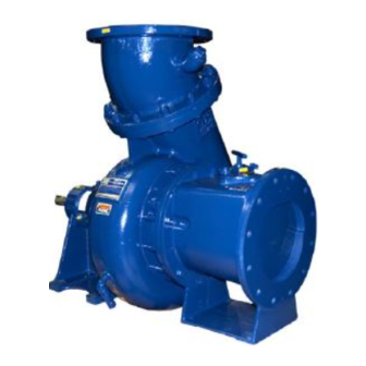
- Page 1 OM‐00701‐04 July 16, 2019 INSTALLATION, OPERATION, AND MAINTENANCE MANUAL WITH PARTS LIST 10 SERIES PUMP MODEL 112A20-B GORMAN‐RUPP PUMPS www.grpumps.com 2019 Gorman‐Rupp Pumps Printed in U.S.A.
- Page 2 Register your new Gorman‐Rupp pump online at www.grpumps.com/register. Valid serial number and e‐mail address required. RECORD YOUR PUMP MODEL AND SERIAL NUMBER Please record your pump model and serial number in the spaces provided below. Your Gorman‐Rupp distributor needs this information when you require parts or service. Pump Model: Serial Number:...
-
Page 3: Table Of Contents
TABLE OF CONTENTS INTRODUCTION ..........PAGE I - 1 SAFETY ‐... - Page 4 TABLE OF CONTENTS (continued) PARTS LIST: Pump Model ............PAGE E - 3 PUMP AND SEAL DISASSEMBLY AND REASSEMBLY .
-
Page 5: Introduction
10 SERIES OM-00701 INTRODUCTION Thank You for purchasing a Gorman‐Rupp pump. HAZARD AND INSTRUCTION Read this manual carefully to learn how to safely DEFINITIONS install and operate your pump. Failure to do so could result in personal injury or damage to the The following are used to alert maintenance per... -
Page 6: Safety - Section A
10 SERIES OM-00701 SAFETY ‐ SECTION A This information applies to 10 Series ba cified entrained solids. Do not attempt sic pumps. Gorman‐Rupp has no con to pump volatile, corrosive or flam trol over or particular knowledge of the mable liquids which may damage the power source which will be used. - Page 7 OM-00701 10 SERIES Do not operate the pump without Do not remove plates, covers, gauges, shields and/or guards in place over the pipe plugs, or fittings from an over drive shafts, belts, and/or couplings, or heated pump. Vapor pressure within the other rotating parts.
-
Page 8: Installation - Section B
10 SERIES OM-00701 INSTALLATION - SECTION B Review all SAFETY information in Section A. specific application. Since the pressure supplied to the pump is critical to performance and safety, Since pump installations are seldom identical, this be sure to limit the incoming pressure to 50% of the... -
Page 9: Positioning Pump
OM-00701 10 SERIES ing, check for loose hardware at mating sur faces. c. Carefully read all tags, decals, and markings The pump assembly can be seriously on the pump assembly, and perform all duties damaged if the chains or cables used to lift indicated. -
Page 10: Gauges
10 SERIES OM-00701 cause excessive vibration, decreased bearing life, should be the eccentric type, and should be in and increased shaft and seal wear. If hose‐type stalled with the flat part of the reducers uppermost lines are used, they should have adequate support to avoid creating air pockets. -
Page 11: Suction Line Positioning
OM-00701 10 SERIES trained air to escape from the liquid before it is shows recommended minimum submergence vs. drawn into the suction inlet. velocity. If two suction lines are installed in a single sump, the flow paths may interact, reducing the efficiency NOTE of one or both pumps. -
Page 12: Bypass Lines
10 SERIES OM-00701 With high discharge heads, it is recommended that a throttling valve and a system check valve be in stalled in the discharge line to protect the pump from excessive shock pressure and reverse rota A bypass line that is returned to a wet well tion when it is stopped. -
Page 13: Automatic Air Release Valve
OM-00701 10 SERIES When mounted at the Gorman‐Rupp factory, driver move plates, covers, gauges, or fittings and pump are aligned before shipment. Misalign from an over‐heated pump. Liquid with ment will occur in transit and handling. Pumps in the pump can reach boiling tempera... -
Page 14: Belt Drives
10 SERIES OM-00701 every 90_. The coupling is in alignment when the belts are a matched set; unmatched sets will cause hubs are the same distance apart at all points (see accelerated belt wear. Figure B-4). MISALIGNED: MISALIGNED: ALIGNED: SHAFTS... -
Page 15: Operation - Section C
OM-00701 10 SERIES OPERATION - SECTION C Review all SAFETY information in Section A. Add liquid to the pump casing when: 1. The pump is being put into service for the Follow the instructions on all tags, labels and first time. -
Page 16: Operation
OM-00701 10 SERIES Consult the operating manual furnished with the Leakage pump power source before attempting to start the power source. No leakage should be visible at pump mating sur faces, or at pump connections or fittings. Keep all If an electric motor is used to drive the pump, re... -
Page 17: Strainer Check
OM-00701 10 SERIES Strainer Check After stopping the pump, disconnect the power source or lock it out to ensure that the pump will re If a suction strainer has been shipped with the main inoperative. pump or installed by the user, check the strainer regularly, and clean it as necessary. -
Page 18: Troubleshooting - Section D
10 SERIES OM-00701 TROUBLESHOOTING - SECTION D Review all SAFETY information in Section A. Before attempting to open or service the pump: 1. Familiarize yourself with this man ual. 2. Disconnect or lock out the power source to ensure that the pump will remain inoperative. - Page 19 OM-00701 10 SERIES TROUBLE POSSIBLE CAUSE PROBABLE REMEDY PUMP STOPS OR Impeller or other wearing parts worn Replace worn or damaged parts. FAILS TO DELIVER or damaged. Check that impeller is properly RATED FLOW OR centered and rotates freely. PRESSURE (cont.) Leaking or worn seal or pump gasket.
-
Page 20: Preventive Maintenance
10 SERIES OM-00701 Record keeping is an essential component of a PREVENTIVE MAINTENANCE good preventive maintenance program. Changes Routine preventive maintenance of the pump will in suction and discharge gauge readings (if so maintain peak operating performance. Since equipped) between regularly scheduled inspec... -
Page 21: Pump Maintenance And Repair - Section E
10 SERIES OM-00701 PUMP MAINTENANCE AND REPAIR ‐ SECTION E MAINTENANCE AND REPAIR OF THE WEARING PARTS OF THE PUMP WILL MAINTAIN PEAK OPERATING PERFORMANCE. STANDARD PERFORMANCE FOR PUMP MODEL 112A20-B Based on 70_ F (21_ C) clear water at sea level Contact the Gorman‐Rupp Company to verify per... - Page 22 OM-00701 10 SERIES PARTS PAGE ILLUSTRATION Figure E-1. Pump Model 112A20-B PAGE E - 2 MAINTENANCE & REPAIR...
- Page 23 10 SERIES OM-00701 PARTS LIST Pump Model 112A20-B (From S/N 1707664 up) If your pump serial number is followed by an “N”, your pump is NOT a standard production model. Contact the Gorman‐Rupp Company to verify part numbers. ITEM PART NAME...
- Page 24 OM-00701 10 SERIES PUMP AND SEAL DISASSEMBLY AND REASSEMBLY Before attempting to open or service the Review all SAFETY information in Section A. pump: 1. Familiarize yourself with this man ual. Follow the instructions on all tags, label and de...
- Page 25 10 SERIES OM-00701 Remove the flat head capscrews (45) and separate Support the pump casing using a suitable hoist the check valve assembly (11) and gasket (10) and sling. from the check valve flange (5). Remove the hardware (24) securing the pump cas...
- Page 26 OM-00701 10 SERIES moval. careful not to drop or damage the seal compo nents when removing the seal plate. Use a dowel or other suitable tool to press the sta tionary element, seat and O‐rings out of the seal plate from the back side.
- Page 27 10 SERIES OM-00701 After removing the shaft and bearings, clean and If bearing replacement is required, use a bearing inspect the bearings in place as follows. puller to remove the bearings from the shaft. Shaft and Bearing Reassembly and Installation Clean and inspect the bearings as indicated in Shaft and Bearing Removal and Disassembly.
- Page 28 OM-00701 10 SERIES BALL LOADING BALL LOADING GROOVE POSITIONED GROOVE POSITIONED TOWARD IMPELLER AWAY FROM IMPELLER LOADING LOADING GROOVE GROOVE DIRECTION OF DIRECTION OF THRUST THRUST INSTALLATION OF NEW DEPARTURE OR INSTALLATION OF MRC/SKF 5300M OR BCA/FEDERAL MOGAL 5300W SERIES BEARINGS...
- Page 29 10 SERIES OM-00701 non‐oil based solvent and a clean, lint‐free tissue. sparks, and flame. Read and follow all Wipe lightly in a concentric pattern to avoid precautions printed on solvent contain scratching the faces. ers. Inspect the impeller shaft for damage. Small...
- Page 30 OM-00701 10 SERIES Lay the seal plate on a flat surface with the impeller Replace the suction plate O‐ring (68) and lubricate side up. Press the oil seal (70) into the seal plate it with light oil or grease. Install the gasket (6) and with the lip positioned as shown in Figure E-1.
- Page 31 10 SERIES OM-00701 LUBRICATION Seal Assembly Fill the seal bottle oiler (37) with SAE No. 30 non‐ Monitor the condition of the bearing lubri detergent oil. Check the oil level regularly and refill cant regularly for evidence of rust or mois...
- Page 32 For Warranty Information, Please Visit www.grpumps.com/warranty or call: U.S.: 419-755-1280 Canada: 519-631-2870 International: +1-419-755-1352 GORMAN‐RUPP PUMPS...
Need help?
Do you have a question about the 10 Series and is the answer not in the manual?
Questions and answers