
Related Manuals for GORMAN-RUPP PUMPS 13A2-B


Summary of Contents for GORMAN-RUPP PUMPS 13A2-B
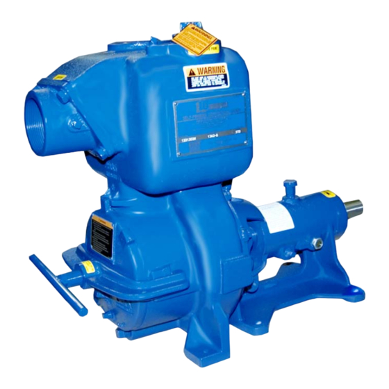
- Page 1 OM‐00621‐10 March 26, 1980 Rev. F 05‐29‐2019 INSTALLATION, OPERATION, AND MAINTENANCE MANUAL WITH PARTS LIST 10 SERIES PUMP MODEL 13A2‐B GORMAN‐RUPP PUMPS www.grpumps.com 1980 Gorman‐Rupp Pumps Printed in U.S.A.
- Page 2 Register your new Gorman‐Rupp pump online at www.grpumps.com Valid serial number and e‐mail address required. RECORD YOUR PUMP MODEL AND SERIAL NUMBER Please record your pump model and serial number in the spaces provided below. Your Gorman‐Rupp distributor needs this information when you require parts or service. Pump Model: Serial Number:...
-
Page 3: Table Of Contents
TABLE OF CONTENTS INTRODUCTION ..........PAGE I - 1 SAFETY ‐... - Page 4 TABLE OF CONTENTS (continued) TROUBLESHOOTING - SECTION D ......PAGE D - 1 PREVENTIVE MAINTENANCE .
-
Page 5: Introduction
10 SERIES OM-00621 INTRODUCTION Thank You for purchasing a Gorman‐Rupp pump. The following are used to alert maintenance per Read this manual carefully to learn how to safely sonnel to procedures which require special atten install and operate your pump. Failure to do so tion, to those which could damage equipment, and could result in personal injury or damage to the to those which could be dangerous to personnel:... -
Page 6: Safety - Section A
10 SERIES OM-00621 SAFETY ‐ SECTION A This information applies to 10 Series ba 5. Close the suction and discharge sic pumps. Gorman‐Rupp has no con valves. trol over or particular knowledge of the 6. Vent the pump slowly and cau power source which will be used. - Page 7 OM-00621 10 SERIES Do not operate the pump without the Do not operate the pump against a shields and/or guards in place over the closed discharge valve for long periods drive shaft, belts, and/or couplings, or of time. If operated against a closed dis other rotating parts.
-
Page 8: Installation - Section B
See Figure 1 for the approximate physical dimen some of the information such as mounting, line sions of this pump. OUTLINE DRAWING Figure 1. Pump Model 13A2-B INSTALLATION PAGE B - 1... -
Page 9: Preinstallation Inspection
OM-00621 10 SERIES PREINSTALLATION INSPECTION POSITIONING PUMP The pump assembly was inspected and tested be fore shipment from the factory. Before installation, inspect the pump for damage which may have oc curred during shipment. Check as follows: Death or serious personal injury and damage to the pump or components a. -
Page 10: Suction And Discharge Piping
10 SERIES OM-00621 Installation closer to the pump may result in erratic SUCTION AND DISCHARGE PIPING readings. SUCTION LINES Pump performance is adversely effected by in To avoid air pockets which could affect pump prim creased suction lift, discharge elevation, and fric ing, the suction line must be as short and direct as tion losses. -
Page 11: Suction Line Positioning
OM-00621 10 SERIES sump at a distance equal to 1‐1/2 times the diame tance equal to at least 3 times the diameter of the ter of the suction line. suction pipe. If there is a liquid flow from an open pipe into the Suction Line Positioning sump, the flow should be kept away from the suc... -
Page 12: Discharge Lines
10 SERIES OM-00621 In low discharge head applications (less than 30 DISCHARGE LINES feet (9,1 m)), it is recommended that the bypass line be run back to the wet well, and located 6 Siphoning inches below the water level or cut‐off point of the low level pump. -
Page 13: Automatic Air Release Valve
OM-00621 10 SERIES AUTOMATIC AIR RELEASE VALVE When properly installed, a Gorman‐Rupp Auto matic Air Release Valve will permit air to escape A manual shut‐off valve should not be through the bypass line and then close automati installed in any bypass line. A manual cally when the pump is fully primed and pumping shut‐off valve may inadvertently be left at full capacity. -
Page 14: Alignment
10 SERIES OM-00621 DISCHARGE PIPE CLEAN‐OUT COVER INSTALL AIR RELEASE VALVE IN HORIZONTAL POSITION DISCHARGE CHECK VALVE 90_ LONG RADIUS ELBOW SUPPORT PUMP DISCHARGE BRACKET SELF‐PRIMING CENTRIFUGAL PUMP BLEED LINE 1” (25,4 MM) DIA. MIN. (CUSTOMER FUR NISHED) DO NOT EX SUCTION TEND BELOW PUMP LINE... -
Page 15: Coupled Drives
OM-00621 10 SERIES Check parallel adjustment by laying a straightedge across both coupling rims at the top, bottom, and side. When the straightedge rests evenly on both halves of the coupling, the coupling is in horizontal Adjusting the alignment in one direction parallel alignment. -
Page 16: V-Belt Tensioning
10 SERIES OM-00621 The ratio of deflection to belt span is 1:64 for both V‐BELT TENSIONING ASA and metric units. Therefore, a belt with a span General Rules of Tensioning of 64 inches would require a deflection of 1 inch at the force shown on the Tables for your particular For new v‐belts, check the tension after 5, 20 and application. - Page 17 OM-00621 10 SERIES Table 1. Sheave Diameter (Inches) Table 2. Sheave Diameter (Millimeters) Deflection Force (Lbs.) Deflection Force (KG.) Belt Deflection Force Belt Deflection Force Uncogged Cogged Uncogged Cogged Hy‐T Belts & Torque‐Flex Hy‐T Belts & Torque‐Flex Uncogged & Machined Uncogged &...
-
Page 18: Operation - Section C
OM-00621 10 SERIES OPERATION - SECTION C Review all SAFETY information in Section A. 1. The pump is being put into service for the first time. Follow the instructions on all tags, labels and 2. The pump has not been used for a consider decals attached to the pump. -
Page 19: Operation
OM-00621 10 SERIES Consult the operating manual furnished with the filled, adjust the throttling valve to the required flow power source before attempting to start the power rate. source. Leakage If an electric motor is used to drive the pump, re move V‐belts, couplings, or otherwise disconnect No leakage should be visible at pump mating sur... -
Page 20: Pump Vacuum Check
OM-00621 10 SERIES maximum permissible operating pressure shown BEARING TEMPERATURE CHECK on the pump performance curve (see Section E, Page 1). Bearings normally run at higher than ambient tem peratures because of heat generated by friction. Temperatures up to 160_F (71_C) are considered Pump Vacuum Check normal for bearings, and they can operate safely to at least 180_F (82_C). - Page 21 10 SERIES OM-00621 TROUBLESHOOTING - SECTION D Review all SAFETY information in Section A. Before attempting to open or service the pump: 1. Familiarize yourself with this manual. 2. Disconnect or lock out the power source to ensure that the pump will remain inoperative.
- Page 22 OM-00621 10 SERIES TROUBLE POSSIBLE CAUSE PROBABLE REMEDY Impeller or other wearing parts worn Replace worn or damaged parts. PUMP STOPS OR FAILS TO DELIVER or damaged. Check that impeller is properly RATED FLOW OR centered and rotates freely. PRESSURE (cont.) Impeller clogged.
- Page 23 10 SERIES OM-00621 equipped) between regularly scheduled inspec PREVENTIVE MAINTENANCE tions can indicate problems that can be corrected Since pump applications are seldom identical, and before system damage or catastrophic failure oc pump wear is directly affected by such things as curs.
- Page 24 PUMP MAINTENANCE AND REPAIR ‐ SECTION E MAINTENANCE AND REPAIR OF THE WEARING PARTS OF THE PUMP WILL MAINTAIN PEAK OPERATING PERFORMANCE. STANDARD PERFORMANCE FOR PUMP MODEL 13A2-B Based on 70_ F (21_ C) clear water at sea level Contact the Gorman‐Rupp Company to verify per...
- Page 25 OM-00621 10 SERIES PARTS PAGE SECTION DRAWING Figure E-1. Pump Model 13A2-B PAGE E - 2 MAINTENANCE & REPAIR...
- Page 26 10 SERIES OM-00621 PARTS LIST Pump Model 13A2-B (From S/N 710664 Up) If your pump serial number is followed by an “N”, your pump is NOT a standard production model. Contact the Gorman‐Rupp Company to verify part numbers. ITEM PART NAME...
- Page 27 OM-00621 10 SERIES PUMP AND SEAL DISASSEMBLY AND REASSEMBLY Review all SAFETY information Section A. Before attempting to open or service the Follow the instructions on all tags, label and de pump: cals attached to the pump. 1. Familiarize yourself with this man This pump requires little service due to its rugged, ual.
- Page 28 10 SERIES OM-00621 back cover gasket (39). Clean the mating surfaces of the back cover plate and pump casing. Inspect the wear plate and replace it if badly scored Use Only Genuine Gorman-Rupp re or worn. To remove the wear plate, disengage the hardware (36 and 37) securing it to the back cover.
- Page 29 OM-00621 10 SERIES Shaft and Bearing Removal and Disassembly Turn Counterclockwise When the pump is properly operated and main tained, the pedestal should not require disassem bly. Disassemble the shaft and bearings only when there is evidence of wear or damage. Lathe Dog Arm “V”...
- Page 30 10 SERIES OM-00621 If bearing replacement is required, use a bearing the shaft, it is recommended that bearings puller to remove the inboard and outboard bear be cleaned and inspected in place. It is ings from the impeller shaft. strongly recommended that the bearings be replaced any time the shaft and bear...
- Page 31 OM-00621 10 SERIES Seal Reassembly and Installation (Figures 1 and 3) When installing the bearings onto the Clean the seal cavity and shaft with a cloth soaked shaft, never press or hit against the outer in fresh cleaning solvent. race, balls, or ball cage. Press only on the inner race.
- Page 32 10 SERIES OM-00621 SEAL PLATE SPRING SEAL LINER STATIONARY ROTATING ELEMENT ELEMENT IMPELLER IMPELLER STATIONARY SHAFT WASHER SPACER SLEEVE IMPELLER SHIMS STATIONARY ELEMENT ROTATING ELEMENT PACKING RINGS Figure 3. Seal Assembly the pedestal (15) using two capscrews and nuts (3/8-16 UNC x 1-1/2 inch long, not supplied). Slide the inboard rotating element into the lubri...
- Page 33 OM-00621 10 SERIES Lubricate the seal assembly as indicated in LU After the face clearance has been set, tighten the BRICATION after the impeller has been installed. nuts (30) securing the pump casing to the pedes tal. Impeller Installation and Adjustment Secure the pump casing to the base with the pre...
- Page 34 10 SERIES OM-00621 Final Pump Assembly Fill the pump casing with clean liquid. Reinstall the fill plug (5) and tighten it. Be sure the pump and power source are securely Refer to OPERATION, Section C, before putting mounted to the base. Reconnect the power source the pump back into service.
- Page 35 OM-00621 10 SERIES For cold weather operation, consult the factory or a lubricant supplier for the recommended grade of oil. Power Source Consult the literature supplied with the power source, or contact your local power source repre sentative. PAGE E - 12 MAINTENANCE &...
- Page 36 For Warranty Information, Please Visit www.grpumps.com/warranty or call: U.S.: 419-755-1280 Canada: 519-631-2870 International: +1-419-755-1352 GORMAN‐RUPP PUMPS...
Need help?
Do you have a question about the 13A2-B and is the answer not in the manual?
Questions and answers