GORMAN-RUPP PUMPS 10 Series Installation, Operation And Maintenance Manual
Hide thumbs
Also See for 10 Series:
Table of Contents
Advertisement
Quick Links
ACDE
COM‐04829‐02
November 27, 2001
Rev. B 10‐30‐2013
INSTALLATION, OPERATION,
AND MAINTENANCE MANUAL
WITH PARTS LIST
10 SERIES PUMPS
MODELS
11 1/2A52-E2 1P , 11 1/2A52-E2 3P
& 11 1/2A52-E2 575/3
THE GORMAN‐RUPP COMPANY D MANSFIELD, OHIO
www.grpumps.com
D
GORMAN‐RUPP OF CANADA LIMITED
ST. THOMAS, ONTARIO, CANADA
Printed in U.S.A.
e
2001 The Gorman‐Rupp Company
Advertisement
Table of Contents

Related Manuals for GORMAN-RUPP PUMPS 10 Series


Summary of Contents for GORMAN-RUPP PUMPS 10 Series
- Page 1 COM‐04829‐02 November 27, 2001 Rev. B 10‐30‐2013 INSTALLATION, OPERATION, AND MAINTENANCE MANUAL WITH PARTS LIST 10 SERIES PUMPS MODELS 11 1/2A52-E2 1P , 11 1/2A52-E2 3P & 11 1/2A52-E2 575/3 THE GORMAN‐RUPP COMPANY D MANSFIELD, OHIO www.grpumps.com GORMAN‐RUPP OF CANADA LIMITED ST.
- Page 2 Register your new Gorman‐Rupp pump online at www.grpumps.com Valid serial number and e‐mail address required. RECORD YOUR PUMP MODEL AND SERIAL NUMBER Please record your pump model and serial number in the spaces provided below. Your Gorman‐Rupp distributor needs this information when you require parts or service. Pump Model: Serial Number:...
-
Page 3: Table Of Contents
TABLE OF CONTENTS INTRODUCTION ..........PAGE I - 1 SAFETY ‐... - Page 4 TABLE OF CONTENTS (continued) PUMP MAINTENANCE AND REPAIR ‐ SECTION E ....PAGE E - 1 STANDARD PERFORMANCE CURVE ........PAGE E - 1 PARTS LISTS: Pump Model...
-
Page 5: Introduction
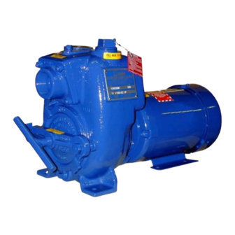
This pump is a 10 Series, semi‐open impeller, self‐ priming centrifugal model with a suction check valve. It is close‐coupled to a 2 H.P ., single phase or three phase, totally enclosed fan‐cooled electric... -
Page 6: Safety - Section A
10 SERIES OM-04829 SAFETY ‐ SECTION A This information applies to 10 Series 6. Vent the pump slowly and cau electric motor driven pumps. Refer to tiously. the manual accompanying the motor 7. Drain the pump. before attempting to begin operation. - Page 7 OM-04829 10 SERIES Do not operate the pump against a Do not install and operate a non‐explo closed discharge valve for long periods sion proof motor in an explosive atmo of time. If operated against a closed dis sphere. Install, connect, and operate charge valve, pump components will the motor in accordance with the Na...
-
Page 8: Installation - Section B
10 SERIES OM-04829 INSTALLATION - SECTION B Review all SAFETY information in Section A. specific application. Since the pressure supplied to the pump is critical to performance and safety, Since pump installations are seldom identical, this be sure to limit the incoming pressure to 50% of the... -
Page 9: Preinstallation Inspection
OM-04829 10 SERIES If the maximum shelf life has been exceeded, or if PREINSTALLATION INSPECTION anything appears to be abnormal, contact your Gorman‐Rupp distributor or the factory to deter The pump assembly was inspected and tested be mine the repair or updating policy. Do not put the fore shipment from the factory. -
Page 10: Suction And Discharge Piping
10 SERIES OM-04829 Installation closer to the pump may result in erratic SUCTION AND DISCHARGE PIPING readings. Pump performance is adversely effected by in SUCTION LINES creased suction lift, discharge elevation, and fric tion losses. See the performance curve on Page To avoid air pockets which could affect pump prim... -
Page 11: Suction Lines In Sumps
OM-04829 10 SERIES Suction Lines In Sumps of one or both pumps. To avoid this, position the suction inlets so that they are separated by a dis If a single suction line is installed in a sump, it tance equal to at least 3 times the diameter of the should be positioned away from the wall of the suction pipe. -
Page 12: Discharge Lines
10 SERIES OM-04829 air from the top of the pump during the priming DISCHARGE LINES process. This may be accomplished by installing a bypass line from the top of the pump, back to the Siphoning source of liquid. The end of the bypass line must be submerged. - Page 13 OM-04829 10 SERIES DISCHARGE PIPE CLEAN‐OUT COVER INSTALL AIR RELEASE VALVE IN HORIZONTAL POSITION DISCHARGE CHECK VALVE 90_ LONG RADIUS ELBOW SUPPORT PUMP DISCHARGE BRACKET SELF‐PRIMING CENTRIFUGAL PUMP BLEED LINE 1” (25,4 MM) DIA. MIN. (CUSTOMER FUR NISHED) DO NOT EX...
-
Page 14: Electrical Connections
10 SERIES OM-04829 ELECTRICAL CONNECTIONS Before connecting the motor to the incoming power, check that the electrical service available Do not install and operate a non‐explo matches the pump motor requirements stamped sion proof motor in an explosive atmo on the motor nameplate. -
Page 15: Operation - Section C
OM-04829 10 SERIES OPERATION - SECTION C Review all SAFETY information in Section A. Add liquid to the pump casing when: 1. The pump is being put into service for the Follow the instructions on all tags, labels and first time. -
Page 16: Operation
OM-04829 10 SERIES Consult the operating manual furnished with the Liquid Temperature And Overheating pump motor before attempting to start the motor. The maximum liquid temperature for this pump is 160_ F (71_C). Do not apply it at a higher operating If rotation is incorrect on a three‐phase motor, have... -
Page 17: Stopping
OM-04829 10 SERIES Open the suction line, and read the vacuum gauge After stopping the pump, disconnect the incoming with the pump primed and at operation speed. power to the motor and lock it out to ensure that the Shut off the pump. The vacuum gauge reading will pump will remain inoperative. -
Page 18: Troubleshooting - Section D
10 SERIES OM-04829 TROUBLESHOOTING - SECTION D Review all SAFETY information in Section A. Before attempting to open or service the pump: 1. Familiarize yourself with this manual. 2. Disconnect the incoming power to the motor and lock it out to ensure that the pump will remain inoperative. - Page 19 OM-04829 10 SERIES TROUBLE POSSIBLE CAUSE PROBABLE REMEDY PUMP STOPS OR Leaking or worn seal or pump gasket. Check pump vacuum. Replace FAILS TO DELIVER leaking or worn seal or gasket. RATED FLOW OR Impeller clogged. Free impeller of debris.
-
Page 20: Preventive Maintenance
10 SERIES OM-04829 equipped) between regularly scheduled inspec PREVENTIVE MAINTENANCE tions can indicate problems that can be corrected Since pump applications are seldom identical, and before system damage or catastrophic failure oc pump wear is directly affected by such things as curs. -
Page 21: Pump Maintenance And Repair - Section E
10 SERIES OM-04829 PUMP MAINTENANCE AND REPAIR ‐ SECTION E MAINTENANCE AND REPAIR OF THE WEARING PARTS OF THE PUMP WILL MAINTAIN PEAK OPERATING PERFORMANCE. STANDARD PERFORMANCE FOR PUMP MODEL 11 1/2A52-E2 ALL PHASES Based on 70_F (21_C) clear water at sea level Contact the Gorman‐Rupp Company to verify per... - Page 22 OM-04829 10 SERIES SECTION DRAWING PARTS PAGE Figure 1. Pump Model 11 1/2A52-E2 All Phases PAGE E - 2 MAINTENANCE & REPAIR...
-
Page 23: Parts Lists
10 SERIES OM-04829 PARTS LIST Pump Model 11 1/2A52-E2 1P , 11 1/2A52-E2 3P & 11 1/2A52-E2 575/3 (From S/N 1235018 Up) If your pump serial number is followed by an “N”, your pump is NOT a standard production model. Contact the Gorman‐Rupp Company to verify part numbers. -
Page 24: Pump And Seal Disassembly And Reassembly
OM-04829 10 SERIES PUMP AND SEAL DISASSEMBLY that the pump will remain inopera AND REASSEMBLY tive. 3. Allow the pump to completely cool if overheated. Review all SAFETY information in Section A. 4. Check the temperature before opening any covers, plates, or Follow the instructions on all tags, label and de... -
Page 25: Pump Casing Removal
10 SERIES OM-04829 Pump Casing Removal rotating portion of the seal off the shaft as a unit. Apply oil to the sleeve and work it under the bel lows. Slide the rotating portion of the seal off the sleeve. To remove the stationary seat, remove the hard... - Page 26 OM-04829 10 SERIES Inspect the seal components for wear, scoring, faces to ensure that they are free of any foreign grooves, and other damage that might cause leak matter. Discard the spring centering washer in age. Clean and polish the shaft sleeve, or replace it cluded with the seal.
-
Page 27: Impeller Installation And Adjustment
10 SERIES OM-04829 Impeller Installation and Adjustment Clean any scales or debris from the contacting sur faces on the pump casing that might prevent a good seal with the back cover. Replace the back Inspect the impeller, and replace it if cracked or cover gasket (26) and slide the back cover assem... -
Page 28: Lubrication
OM-04829 10 SERIES Motor LUBRICATION Seal Assembly Consult the literature supplied with the motor, or contact your local motor representative. The seal assembly is lubricated by the medium be ing pumped, and no additional lubrication is re quired. PAGE E - 8... - Page 29 For Warranty Information, Please Visit www.grpumps.com/warranty or call: U.S.: 419-755-1280 Canada: 519-631-2870 International: +1-419-755-1352 GORMAN‐RUPP PUMPS...
Need help?
Do you have a question about the 10 Series and is the answer not in the manual?
Questions and answers