GORMAN-RUPP PUMPS 10 Series Installation, Operation, And Maintenance Manual With Parts List
Hide thumbs
Also See for 10 Series:

Related Manuals for GORMAN-RUPP PUMPS 10 Series


Summary of Contents for GORMAN-RUPP PUMPS 10 Series
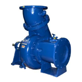
- Page 1 OM-06754-01 March 23, 2015 INSTALLATION, OPERATION, AND MAINTENANCE MANUAL WITH PARTS LIST 10 SERIES PUMP MODEL 16C2-QSF2.8P FT4 GORMAN‐RUPP PUMPS www.grpumps.com 2015 Gorman‐Rupp Pumps Printed in U.S.A.
- Page 2 Register your new Gorman‐Rupp pump online at www.grpumps.com Valid serial number and e‐mail address required. The engine exhaust from this product contains chemicals known to the State of California to cause cancer, birth defects or other reproductive harm. RECORD YOUR PUMP MODEL AND SERIAL NUMBER Please record your pump model and serial number in the spaces provided below.
-
Page 3: Table Of Contents
TABLE OF CONTENTS INTRODUCTION ..........PAGE I - 1 SAFETY - SECTION A . - Page 4 TABLE OF CONTENTS (continued) Seal Cavity and Bearing Lubrication ........PAGE C - 4 Bearing Temperature Check .
-
Page 5: Introduction
10 SERIES OM-06754 INTRODUCTION Thank You for purchasing a Gorman‐Rupp pump. HAZARD AND INSTRUCTION Read this manual carefully to learn how to safely DEFINITIONS install and operate your pump. Failure to do so could result in personal injury or damage to the The following are used to alert maintenance per... -
Page 6: Safety - Section A
10 SERIES OM-06754 SAFETY - SECTION A This information applies to 10 Series en any liquids which may damage the gine driven pumps. Refer to the manual pump or endanger personnel as a result accompanying the engine before at of pump failure. - Page 7 10 SERIES OM-06754 pipe plugs, or fittings from an over heated pump. Vapor pressure within the pump can cause parts being disen gaged to be ejected with great force. Al Fuel used by internal combustion en low the pump to cool before servicing.
-
Page 8: Installation - Section B
10 SERIES OM-06754 INSTALLATION - SECTION B Review all SAFETY information in Section A. to the pump is critical to performance and safety, be sure to limit the incoming pressure to 50% of Since pump installations are seldom identical, this... -
Page 9: Battery Specifications And Installation
OM-06754 10 SERIES ing, check for loose hardware at mating sur Connect and tighten the positive cable first, then faces. the negative cable. c. Carefully read all tags, decals, and markings POSITIONING PUMP on the pump assembly, and follow the instruc... -
Page 10: Clearance
10 SERIES OM-06754 only; however, the engine manufacturer should be to secure them when filled with liquid and under consulted for continuous operation at angles pressure. greater than 15 Gauges Clearance Most pumps are drilled and tapped for installing discharge pressure and vacuum suction gauges. If... -
Page 11: Sealing
OM-06754 10 SERIES Sealing of the suction pipe. The baffle will allow entrained air to escape from the liquid before it is drawn into Since even a slight leak will affect priming, head, the suction inlet. and capacity, especially when operating with a... -
Page 12: Discharge Lines
10 SERIES OM-06754 DISCHARGE LINES In low discharge head applications (less than 30 feet (9,1 m)), it is recommended that the bypass line be run back to the wet well, and located 6 Siphoning inches below the water level or cut‐off point of the low level pump. -
Page 13: Automatic Air Release Valve
OM-06754 10 SERIES through the bypass line and then close automati cally when the pump is fully primed and pumping at full capacity. A manual shut‐off valve should not be installed in any bypass line. A manual shut‐off valve may inadvertently be left closed during operation. -
Page 14: Alignment
10 SERIES OM-06754 Connect the valve outlet to a bleed line which fold pipe. Contact your Gorman‐Rupp distributor or slopes back to the wet well or sump. The bleed line the Gorman‐Rupp Company for information about must be the same size as the outlet opening or installation of an Automatic Air Release Valve for larger, depending on which Air Release Valve is be... -
Page 15: Operation - Section C
OM-06754 10 SERIES OPERATION - SECTION C OPERATION Review all SAFETY information in Section A. Make sure the pump is level. Lower jack Follow the instructions on all tags, labels and stands and chock the wheels, if so decals attached to the pump. -
Page 16: Routine Operation
OM-06754 10 SERIES Add liquid to the pump casing when: continuous operating speed for this pump. 1. The pump is being put into service for the first time. A Gorman‐Rupp automatic air release valve may 2. The pump has not been used for a consider... -
Page 17: Operation In Extreme Heat
OM-06754 10 SERIES Pump Vacuum Check Read the vacuum gauge with the pump primed and at operation speed. Shut off the pump. The Do not operate the pump against a vacuum gauge reading will immediately drop pro closed discharge throttling valve for portionate to static suction lift, and should then sta... -
Page 18: Stopping
OM-06754 10 SERIES Never introduce air or steam pressure into the pump casing or piping to remove a blockage. This could result in personal injury or damage to the equipment. If backflushing is absolutely neces Never disconnect any of the safety shut... - Page 19 OM-06754 10 SERIES Engine Fuel Filter operated under extremely dusty conditions, change the filter more frequently. Consult the manual accompanying the engine, COLD WEATHER PRESERVATION and change the fuel filter periodically as indicated. If operated under extremely dusty and/or humid In below freezing conditions, drain the pump to conditions, change the filter more frequently.
- Page 20 OM-06754 10 SERIES TROUBLESHOOTING - SECTION D Review all SAFETY information in Section A. 5. Close the suction and discharge valves. 6. Vent the pump slowly and cau tiously. 7. Drain the pump. Before attempting to open or service the pump: 1.
- Page 21 OM-06754 10 SERIES TROUBLE POSSIBLE CAUSE PROBABLE REMEDY PUMP STOPS OR Suction intake not submerged at Check installation and correct sub FAILS TO DELIVER proper level or sump too small. mergence as needed. RATED FLOW OR Impeller or other wearing parts worn Replace worn or damaged parts.
- Page 22 OM-06754 10 SERIES PREVENTIVE MAINTENANCE equipped) between regularly scheduled inspec tions can indicate problems that can be corrected Since pump applications are seldom identical, and before system damage or catastrophic failure oc pump wear is directly affected by such things as curs.
- Page 23 OM-06754 10 SERIES PUMP MAINTENANCE AND REPAIR - SECTION E MAINTENANCE AND REPAIR OF THE WEARING PARTS OF THE PUMP WILL MAINTAIN PEAK OPERATING PERFORMANCE. STANDARD PERFORMANCE FOR PUMP MODEL 16C2-QSF2.8P FT4 Based on 70 F (21 C) clear water at sea level Contact the Gorman‐Rupp Company to verify per...
- Page 24 OM-06754 10 SERIES PARTS PAGE ILLUSTRATION Figure 1. Pump Model 16C2-QSF2.8P FT4 PAGE E - 2 MAINTENANCE & REPAIR...
- Page 25 OM-06754 10 SERIES PARTS LIST Pump Model 16C2-QSF2.8P FT4 (From S/N 1646046 Up) If your pump serial number is followed by an “N”, your pump is NOT a standard production model. Contact the Gorman‐Rupp Company to verify part numbers. ITEM...
- Page 26 OM-06754 10 SERIES ILLUSTRATION Figure E-2. Power Unit Kit PAGE E - 4 MAINTENANCE & REPAIR...
- Page 27 OM-06754 10 SERIES PARTS LIST Power Unit Kit ITEM PART PART NAME NUMBER BASE/FUEL TANK ASSEMBLY 41553-029 24150 CUMMINS QSF2.8P FT4 ENGINE 29216-401 CONTROL PANEL INSTALLATION KIT 48122-553 LIFTING BAIL KIT 48274-811 LOCK WASHER J10 15991 HEX NUT D10 15991...
- Page 28 OM-06754 10 SERIES ILLUSTRATION Figure 3. Pump End Assembly PAGE E - 6 MAINTENANCE & REPAIR...
- Page 29 OM-06754 10 SERIES PARTS LIST Pump End Assembly ITEM PART NAME PART ITEM PART NAME PART NUMBER NUMBER PUMP CASING SEE NOTE BELOW MACHINE BOLT A1014 15991 CLAMP BAR SCREW 31912-009 15000 BACK CVR PLATE ASSY 42111-935 -PIPE PLUG P04 15079...
- Page 30 OM-06754 10 SERIES ILLUSTRATION Figure 4. Drive Assembly PARTS LIST ITEM PART PART NAME NUMBER COUPLING KIT 48112-001 -BUSHING 24131-345 -COUPLING ASSEMBLY 44165-011 HEX HD CAPSCREW BD0605 15991 HEX HD CAPSCREW 22645-164 HEX HD CAPSCREW 22645-170 LOCKWASHER J06 15991 LOCKWASHER...
- Page 31 OM-06754 10 SERIES PUMP AND SEAL DISASSEMBLY AND REASSEMBLY Review all SAFETY information in Section A. Before attempting to open or service the pump: Follow the instructions on all tags, label and de 1. Familiarize yourself with this man cals attached to the pump.
- Page 32 OM-06754 10 SERIES Remove the cover clamp screw (17) and clamp bar (16) securing the back cover. Pull the back cover and assembled wear plate from the pump casing (1). Inspect the back cover gasket (13) and replace Do not attempt to lift the complete pump it if damaged or worn.
- Page 33 OM-06754 10 SERIES Reach through the suction port and wedge a block of wood between the vanes of the impeller and the pump casing to prevent rotation. Do not attempt to lift the complete pump If removed, install the shaft key (38) in the shaft unit using the lifting eye.
- Page 34 OM-06754 10 SERIES impeller through the back cover opening and using strongly recommended that the bearings a pair of stiff wires with hooked ends to pull the seal be replaced any time the shaft and bear parts out of the seal plate.
- Page 35 OM-06754 10 SERIES Position the inboard oil seal (51A) in the intermedi ings should never be heated with a direct flame or ate housing bore with the lip positioned as shown directly on a hot plate. in Figure 3. Press the oil seal into the housing until...
- Page 36 OM-06754 10 SERIES the bearing bore, push against the outer precautions printed on solvent contain race. Never hit the balls or ball cage. ers. The seal is not normally reused because wear pat Apply a light coating of oil to the lip of the outboard...
- Page 37 OM-06754 10 SERIES PIPE NIPPLE PACKING RINGS SEAL PLATE SEAL LINER IMPELLER ADJ SHIMS ROTATING ELEMENT IMPELLER SHAFT STATIONARY SEAL SEAT IMPELLER SHAFT SLEEVE STATIONARY WASHER STATIONARY WASHER SPRING Figure 7. Seal Assembly lubricant hole with the intermediate opening and temporarily secure the seal plate to the intermedi...
- Page 38 OM-06754 10 SERIES Impeller Installation and Adjustment A clearance of .010 to .020 inch (0,25 to 0,51 mm) between the impeller and the wear plate is also rec (Figure 3) ommended for maximum pump efficiency. This clearance must be set after installing the back...
- Page 39 OM-06754 10 SERIES Suction Check Valve Installation (Figure 3) Inspect the check valve assembly (28) and replace Make certain that the flexible portion of the it if badly worn. coupling is mounted as shown in Figure 4. This is critical. If the coupling is not prop...
- Page 40 OM-06754 10 SERIES surface which contacts the pump casing. This ac Be sure the pump end and engine have been tion will reduce rust and scale build‐up. properly lubricated, see LUBRICATION. Remove the fill cover assembly (31). Fill the pump casing with clean liquid.
- Page 41 OM-06754 10 SERIES Under normal conditions, drain the intermediate ture condensation. This is especially im once each year and refill with approximately 7‐1/2 portant in areas where variable hot and ounces (22 mL) of clean oil. Change the oil more cold temperatures are common.
- Page 42 For Warranty Information, Please Visit www.grpumps.com/warranty or call: U.S.: 419-755-1280 Canada: 519-631-2870 International: +1-419-755-1352 GORMAN‐RUPP PUMPS...
Need help?
Do you have a question about the 10 Series and is the answer not in the manual?
Questions and answers