Table of Contents
Advertisement
ADVANCED Series Thermostats
AC 150
AC 200
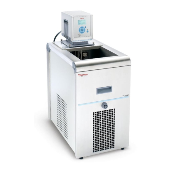
ARCTIC Series Refrigerated Bath Circulators
A 5B
A 10
A 10B
A 25
A 25B
A 28
A 28F
A 24B
A 40
GLACIER Series Refrigerated Bath Circulators
G 50
SAHARA Series Heating Bath Circulators
S 3
S 12T
S 7
S 19T
S 13
S 15
S 21
S 30
S 45
S 49
S 14P
S 21P
Thermo Scientific
Laboratory
Temperature
Control Products
Manual Part Number U01046
Rev. 07/07/10
Visit our Web site at:
http://www.thermoscientific.com/tc
Product Service Information, Applications
Notes, MSDS Forms, e-mail.
Advertisement
Table of Contents

Related Manuals for Thermo Scientific ADVANCED Series


Summary of Contents for Thermo Scientific ADVANCED Series
- Page 1 Thermo Scientific Laboratory Temperature Control Products Manual Part Number U01046 Rev. 07/07/10 ADVANCED Series Thermostats AC 150 AC 200 ARCTIC Series Refrigerated Bath Circulators A 5B A 10 A 10B A 25 A 25B A 28 A 28F A 24B...
- Page 2 Thermo Fisher Scientific Sales, Service, and Customer Support 25 Nimble Hill Road 25 Nimble Hill Road Newington, NH 03801 Newington, NH 03801 Tel : (800) 258-0830 or Tel: (800) 258-0830 (603) 436-9444 Sales: 8:00 am to 5:00 pm Fax : (603) 436-8411 Service and Support: 8:00 am to 6:00 pm Monday www.thermoscientific.com/tc through Friday (Eastern Time)
-
Page 3: Table Of Contents
Additional Fluid Precautions ................3-9 Filling Requirements ..................3-12 Draining ......................3-12 ................4-1 Section 4 Operation ADVANCED Thermostat ................4-1 Setup ........................4-2 Initial Start Up ....................4-2 Daily Start Up .....................4-3 Status Display .....................4-3 Changing the Setpoint ..................4-4 Menu Displays ....................4-5 Menu ........................4-6 Menu Tree ......................4-7 Thermo Scientific... - Page 4 Optional Serial Communication Adapter............5-4 Tubing ........................5-5 ............6-1 Section 6 Preventive Maintenance Cleaning ......................6-1 Condenser Fins ....................6-1 Testing the Safety Features ................6-2 Section 7 Troubleshooting ....................7-1 Error Displays ....................7-1 Appendix Serial Communications ..................A-1 Declaration of Conformity Return Materials Authorization Form Warranty Thermo Scientific...
-
Page 5: Preface
Thermo Fisher Scientific has contracted with one or more recycling/ disposal companies in each EU Member State, dispose of or recycle this product through them. Further information on Thermo Fisher Scientific’s compliance with these Directives is available at: www.thermo.com/WEEERoHS Thermo Scientific... -
Page 6: After-Sale Support
Warranty Thermo Scientific Laboratory Temperature Control Products have a warranty against defective parts and workmanship for 36 months from date of shipment. See back page of this manual for more details. -
Page 7: Safety
Observe all warning labels. Never remove warning labels. Refrigerated units should be left in an upright position for 24 hours at room temperature before starting. This will ensure the lubrication oil has drained back into the compressor. Thermo Scientific... - Page 8 Do not clean the unit with solvents, a soft cloth and water is normally sufficient. Refer service and repairs to a qualified technician. Performance of installation, operation, or maintenance procedures other than those described in this manual may result in a hazardous situation and will void the manufacturer's warranty. Thermo Scientific...
-
Page 9: General Information
General Information Section 2 Description The Thermo Scientific ADVANCED Series of thermostats are used with refrigerated and heated baths. All thermostats can pump to an external system. All controllers have a digital display and easy-to-use touch pad, five programmable setpoint temperatures, acoustic and optical alarms, and offer adjustable high temperature protection. -
Page 10: Bath/Circulator Specifications
200 V/50 Hz 200 V/60 Hz or (Voltage ±10%) 208 V/60 Hz or 230 V/50 Hz *Add ~26 mm (1 inch) to D for drain fitting. **See Section 3 for additional information. • Thermo Fisher Scientific reserves the right to change specifications without notice. Thermo Scientific... - Page 11 36.2 44.7 53.4 *Lower temperature ranges available with supplemental cooling. **Add ~26 mm (1 inch) to D for drain fitting. ***See Section 3 for additional information. • Thermo Fisher Scientific reserves the right to change specifications without notice. Thermo Scientific...
-
Page 12: Wetted Materials
• Thermo Fisher Scientific reserves the right to change specifications without notice. Wetted Materials ADVANCED Thermostat Stainless Steel Baths/Circulators Viton Stainless Steel 316 EPDM Stainless Steel 304 Ryton EPDM (drain fitting) Ultem Ryton Vectra Zotek-N (cover seal) Stainless Steel Transparent Acrylic Baths/Circulators Poly-acryl Polyphenylene oxide (PPO) Baths/ Circulators Polyphenylenoxid Thermo Scientific... -
Page 13: Installation
Refrigerated units should be left in an upright position for 24 hours at CAUTION room temperature before starting. This will ensure the lubrication oil has drained back into the compressor. Thermo Scientific... -
Page 14: Ventilation
The outlet must be rated as suitable for the total power consumption of the unit, see next page. NOTE If a bath and thermostat were purchased separately, follow the elec- trical requirements listed on the bath nameplate. Thermo Scientific... - Page 15 100/50-60/1 1525 N5-20 230/50/1 2600 Country Specific All Heated 115/60/1 1300 N5-20 Baths/Circulators 100/50-60/1 1300 N5-20 230/50/1 2135 Country Specific 1. Volts ± 10% 2. Maximum amp draw 20 Amp Outlet 15 Amp Outlet (16 Amp) (12 Amp) Thermo Scientific...
- Page 16 Ensure the electrical cords do not come in contact with any of the plumbing connections or tubing. • Install the supplied communications cable between the thermostat and the bath RJ45 connectors (similar to Ethernet). Communication Thermostat Cable required for proper communication between the bath and the thermostat. Bath Communication Thermo Scientific...
-
Page 17: External Circulation
Section 4 for additional information. 11 12 13 14 15 6 7 8 9 10 1 2 3 4 5 Instructions for installing the USB driver are provided on a disc included with USB Port the accessory kit. (AC 200 only) Thermo Scientific... -
Page 18: Tubing Requirements
• secure all tube connections using clamps When using the internal bath only, the plumbing connections can be closed with the supplied plate and union nuts. Thermo Scientific... -
Page 19: Tubing
Section 3 Installation Tubing Tubing for Thermo Scientific temperature control systems is optional. Please select the proper tubing from the table shown in Section 5. CAUTION Ensure the tubing you select will meet your maximum temperature and pressure requirements. ... -
Page 20: Fluids
5°C lower than the operating temperature of the particular application. This will prevent the water/glycol from gelling (freezing) near the evaporating coil. Excess glycol deteriorates the temperature accuracy due to its high viscosity. Thermo Scientific... -
Page 21: Additional Fluid Precautions
• Avoid spattering on any of the unit's components, always When adding, point the opening of a container away from yourself. • Use fume hoods. • Do not allow any ignition sources in the vicinity. Thermo Scientific... - Page 22 Reacts with Silicone Silicone Silicone Rubber Copper Copper Silicone Light Light metals metals Bronze Bronze EC-Safety Data Sheets will be delivered together with each container of liquid. 3-10 Thermo Scientific...
- Page 23 Recommendation: Initially fill the tank with distilled or deionized water. Do not use untreated tap water as the total ionized solids level may be too high. This will reduce the electrolytic potential of the water and prevent or reduce the galvanic corrosion observed. 3-11 Thermo Scientific...
-
Page 24: Filling Requirements
In this case, the drain fitting can be screwed back into the unit. Attaching the cap onto the fitting will aid in installation. If required, contact us for additional information. Installed Drain Fitting with Cap Removed 3-12 Thermo Scientific... -
Page 25: Operation
Operation Section 4 ADVANCED The Thermo Scientific ADVANCED Series of thermostats have a digital display and easy-to-use touch pad, five programmable setpoint temperatures, Thermostat acoustic and optical alarms and some units offer adjustable high temperature protection. This label indicates read the instruction manual before starting the unit. -
Page 26: Setup
D o not run the unit until fluid is added to the bath. Have extra fluid Initial Start Up on hand. If the unit will not start refer to Section 6 Troubleshooting. • For refrigerated units, place the circuit protector located on the rear of the bath to the I position. • For all units, place the circuit protector located on the rear of the thermostat to the I position. • Press . The thermostat will momentarily Thermo Scientific display: • And then the Start Display will appear. Menu Highlighted Start Symbol Reservoir +020.00 Fluid Indicates the controller Temperature +024.29 °C is displaying the internal temperature probe sensor Internal Temp.. -
Page 27: Daily Start Up
Status Display. Temperature Scale Sensor Heater Duty Cycle °C (in) Refrigeration Duty Cycle Water (refrigerated units) + 0 2 4 . 2 9 Reservoir Fluid Temperature Reservoir Fluid If desired, press again to return to the Start Display. Thermo Scientific... -
Page 28: Changing The Setpoint
Once all the desired changes are made, press to save the change. NOTE Using this procedure also changes the setpoint's stored value. NOTE The setpoint can be changed with the unit running. Thermo Scientific... -
Page 29: Menu Displays
Basic Settings Editor App. Settings Settings Password/Reset System Menu Installation See page 4-12. Menu Adjustment Editor Calibration Settings Interfaces System Accessory Installation Menu Interfaces See page 4-16. Menu Servicing Editor Information Settings Diagnosis System Menu Installation See page 4-18. Thermo Scientific... -
Page 30: Menu
1. From any submenu display, use the down 2. Press to return to the Main Menu Menu arrow button to highlight Display. Menu Setpoint Ramp Program Editor Auto start Settings Timer start System Menu Installation NOTE is not operable from the Menu line. Thermo Scientific... - Page 31 Section 4 Operation Thermo Scientific...
-
Page 32: Editor - Setpoints
Once all the desired changes are made, press to save Setpoint +xxx.x the changes. RTA int +xx.xx RTA ext +xx.xx Menu Thermo Scientific... -
Page 33: Editor Ramp Program
4. Use the arrow buttons to highlight 3. Press to display the submenu. Program. Setpoints Setpoints Ramp Program Ramp Program Auto start Auto start Timer start Timer start Menu Menu 5. Press to display: Edit ramp Edit step Menu Thermo Scientific... - Page 34 9. After all the desired steps are built, keep press- until the Start Display appears. Menu +020.00 +024.29 °C Internal Temp.. Settings - You can enable an alarm to sound when each step and/or the program is complete, see Basic Settings in this section. 4-10 Thermo Scientific...
-
Page 35: Running A Ramp Program
+020.00 The program does not start until the process fluid +024.29 °C Step 1 Start Temp temperature is at the ± Variance Internal Temp.. ramp1 MENU +020.00 +024.29 °C Internal Temp.. Thermo Scientific 4-11... - Page 36 For example on a program which ends with the bath at 25°C the bath will continue to hold this setpoint. Changing from ramp mode to setpoint mode and then changing the setpoint to 20°C has no effect, the bath will continue to hold 25°C. 4-12 Thermo Scientific...
-
Page 37: Editor Auto Start
To set the current time/date see the next page. Timer 2. The second is used to set the timer 1. Press to toggle between Start Time/Date Stop Time/Date When enabled highlight the second Timer. Start Time/Date Timer 12:00:00 Timer 01/01/2010 Stop Time Date Menu Menu Thermo Scientific 4-13... -
Page 38: Settings - Basic Settings
Temp. Unit RAMP Prog. End Temp. Resolution RAMP Step End Display Contrast Safety FAULT Backlight Menu Menu Display Contrast Backlight follow the instructions that appear on the screen. Backlight is either on or off. 4-14 Thermo Scientific... -
Page 39: Settings - App. Settings - Limits
HTemp LIMIT HTemp LIMIT xxx.x xxx. LTemp LIMIT xxx.x Menu Menu System Temp. Limit NOTE The is based on the fluid used, the system performance criteria and the thermostat model. It cannot be changed, see page 4-17. Thermo Scientific 4-15... - Page 40 Define safe state Define Safe Temp Menu Menu Define Safe Temp is used to set the 12. Press to change the setpoint. safety setpoint. Define Limits Safe SP +xxx.xx Define safe state Define Safe Temp Menu Menu 4-16 Thermo Scientific...
-
Page 41: Settings - App. Settings - Fluids Type
Settings - Password/Reset Password/Reset is used to reset the thermostat back to factory preset values. NOTE Password is used only by a qualified technician. Thermo Scientific 4-17... -
Page 42: System Adjustment
Menu Menu Lev3 Highlight the desired level to change the setting. Use to select and enable the high level warning. Lev2 LEV1 cannot be changed. Use to select and enable the low level warning. See Section 6. 4-18 Thermo Scientific... -
Page 43: System - Calibration
Repeat for the other two points. System - Interfaces System Interfaces is used to view the serial communications baud rate or turn the Namur Proto- . This feature is optional. For additional information refer to the Appendix. Thermo Scientific 4-19... -
Page 44: System - Accessory
7. With highlighted, press to display the options. Booster Pump Selection Solenoid Valve Activation Booster Heater Auto Refill Menu Menu External Analog Box The optional installation/operation is explained in a separate document that ships with the box. 4-20 Thermo Scientific... -
Page 45: Installation - Information
Hours +xxxxx Power Up Heater Pump Menu Menu Installation - Diagnosis Installation - Diagnosis is used by a qualified technician to troubleshoot the thermostat. Thermo Scientific 4-21... -
Page 46: Stopping The Unit
The circuit protector(s) located on the rear of the component(s) is CAUTION not intended to act as a disconnecting means. NOTE When quickly restarting refrigerated units, the compressor may Restarting take up to 10 minutes before it starts to operate. 4-22 Thermo Scientific... -
Page 47: Accessories
NOTE the long end of the stack is in- Secure the stacks to the platform. stalled into the hole on the platform as shown. Insert the sockets into the holes on the top of the bridge. Secure the sockets to the bridge using a M15 nut on the bottom of each socket. Slide the stacks up and through the sockets on the bridge. Install a male knurled nut into each socket and install a female knurled nut to the top of the stack. Place the assembly in the bath and secure it to the unit using the four Torx head screws. Place the thermostat on the bridge and secure it using the four thumbscrews, hand tight. Place the lifting platform to the desired position and lock it by using the male knurled nuts. Female Knurled Nut (0032720) Socket (0032718) Male Knurled Nut (0032721) Bridge Position Stack (0032325) M15 Nut (9000144) Platform(Typical) Thermo Scientific... - Page 48 Always turn off the unit and disconnect the power cord from the CAUTION power source before installing the bridge. Undo the four thumbscrews securing the thermostat to the top panel and remove the thermostat. Undo the four Phillips Head screws securing the top panel to the bath and remove it. Turn the old panel over and note the placement of its three gaskets. Using the old panel as a template, install the three supplied gaskets in the same position on the new panel. NOTE Place the panels on a soft clean cloth, their stainless steel surfaces are susceptible to scratching. Place the immersion cooler bridge on the bath and secure it to the unit using the four Phillips Head screws. Place the thermostat on the top panel and secure it using the four thumbscrews, hand tight. Remove the two screws securing the "dummy" panel to the immersion cooler bridge. Insert the immersion circulator head through the hole. Secure the head to the top panel using the two supplied panels. Immersion Cooler Head Thermo Scientific...
- Page 49 Optional Stainless Steel Insert Racks: A5B, A10B, A24B, S49, S19T, S14P, S21P (283 x 145 mm) A25B, A410B, S21, S30 (160 x 145 mm) S13, S12T (160 x 100 mm) • 10 mm test tube holes • 16 mm test tube holes • 25 mm test tube holes • No holes Thermo Scientific...
- Page 50 GND = Signal ground 6 - 9 No connection TX = Transmitted data from thermostat RX = Received data to thermostat. If the unit already has a communication cable installed, remove the cable from the rear of the thermostat and plug that cable into PORT 2 on the adapter. PORT 1 RS232 PORT2 Plug the supplied cable into PORT 1 on the adapter and the other end into the thermostat. Regardless of the configuration, the supplied cable always goes from the thermostat to PORT 1. Plug the supplied serial communications cable into the communication port on the adapter and then the other end into your computer. If desired, use the supplied Velcro tape to attach the adapter to a ® convenient location on the unit. Thermo Scientific...
-
Page 51: Tubing
Foam rubber insulation for PVC, Viton, Silicone and Perbunan tubes 8 mm i.d. (available per meter) 806-0373 12 mm i.d. (available per meter) 806-0374 Fittings for plastic tubing 8 mm i.d. 001-1209 12 mm i.d. 001-1210 Coupling nut 001-0797 Thermo Scientific... - Page 52 Section 5 Accessories Thermo Scientific...
-
Page 53: Preventive Maintenance
1 Remove the condenser panel. 2 Clean fins with brush or similar tool. 3 Replace the panel. For all other refrigerated baths: Clean the fins with compressed air. For extreme soiling a qualified technician will need to remove the cooling compressor casing. Thermo Scientific... -
Page 54: Testing The Safety Features
65°C or 80°C. Low liquid level protection With the unit on, slowly drain the bath fluid (use a drainage tap if necessary) and ensure the unit shuts down. If not, have the unit checked by qualified a technician. Thermo Scientific... -
Page 55: Troubleshooting
Sales, Service and Customer Support • the refrigeration may need servicing, Refrigeration FAULT contact our Sales, Service and please remove reason Customer Support and press ENTER to clear message Thermo Scientific... - Page 56 Temp. Sensor int. SHORT! Temp. Sensor int. OPEN! temperature sensor please remove reason please remove reason • contact our Sales, Service and and press ENTER and press ENTER Customer Support to clear message to clear message Thermo Scientific...
-
Page 57: Appendix
Line feed character Fxxx Failure code F000 to F255 Examples: W HA 0 85.5 Write parameter HA 0 with the value 85,5 R LA 0 Read parameter LA 0 LA +10.00 LA 0 has a value of 10,00 Thermo Scientific... - Page 58 Write internal RTA of setpoint 4 W C4 <value> Read internal RTA of setpoint 4 R C4 C4 <value> Write internal RTA of setpoint 5 W C5 <value> Read internal RTA of setpoint 5 R C5 C5 <value> Thermo Scientific...
- Page 59 RMA (Return Materials Authorization) Formular / RMA Form Die Annahme Ihres Gerätes/Ihrer Komponenten in unserem Hause kann nur erfolgen, wenn eine korrekt und vollständig aus- gefüllte Erklärung mit einer gültigen RMA-Nr. vorliegt. Ist das nicht der Fall, kommt es leider zu Verzögerungen bzw. muss die Ware zurückgewiesen werden.
- Page 60 Warranty Thermo Fisher Scientific warrants for 36 months from date of shipment the Thermo Scientific ADVANCED series of Thermostats, ARCTIC refrigerated bath circulators, and SAHARA heated bath circulators according to the following terms. Any part of the unit manufactured or supplied by Thermo Fisher Scientific and found in the reasonable judg- ment of Thermo Fisher to be defective in material or workmanship will be repaired at an authorized Thermo Fisher Repair Depot without charge for parts or labor.
Need help?
Do you have a question about the ADVANCED Series and is the answer not in the manual?
Questions and answers