
Subscribe to Our Youtube Channel
Related Manuals for nvent Schroff 20836-820


Summary of Contents for nvent Schroff 20836-820
- Page 1 VME64x System Subrack 8 U User’s Manual Product No.: 20836-820 Revision: R1.1, November 14, 2008 Doc-No: 63972-158...
- Page 2 Rev. Date updated Change R1.0 November 19, 2007 Initial release R1.1 November 14, 2008 Part no. FCM added Impressum: Schroff GmbH D-75334 Straubenhardt, Germany The details in this manual have been carefully compiled and checked - supported by certified Quality Management System to EN ISO 9001/2000 The company cannot accept any liability for errors or misprints.
-
Page 3: Table Of Contents
VME64x System Subrack 8 U 20836-820 Table of Contents Safety ......................... 1 Intended Application .................... 1 Safety Instructions ....................2 Safety Symbols used in this document..............2 General Safety Precautions................. 2 References and Architecture Specifications ............3 Product Definition..................... 4 Mechanical Overview................... - Page 4 VME64x System Subrack 8 U 20836-820 www.schroff.biz R1.1, November 14, 2008...
-
Page 5: Safety
VME64x System Subrack 8 U Safety 20836-820 1 Safety 1.1 Intended Application The VME system subrack, described in this manual, is intended as a platform for a microcomputer system based on the VME bus system (VME (VITA 1-1994) and VME64x (VITA 1.1-1997)). The VME64x system subracks are designed for protection class IP 20 and can be used only in the resp. -
Page 6: Safety Instructions
VME64x System Subrack 8 U Safety 20836-820 1.2 Safety Instructions The intended audience of this User’s Manual is system integrators and hardware/software engineers. 1.3 Safety Symbols used in this document Hazardous voltage! This is the electrical hazard symbol. It indicates that there are dangerous voltages inside the Shelf. -
Page 7: References And Architecture Specifications
VME64x System Subrack 8 U Safety 20836-820 1.5 References and Architecture Specifications • User Manual VME64x Backplanes Order no.: 73972-103 • Short Form User Manual VME64x Backplanes Order no.: 73972-074 • User Manual Fan Control Module (FCM) Order no.: 73972-083 •... -
Page 8: Product Definition
VME64x System Subrack 8 U Product Definition 20836-820 2 Product Definition The Schroff VME64x subrack system consists of: • A shielded 19“ subrack with front assembly area for 6 U front boards according to VME64x Standard (VITA 1.1-1997) • Rear assembly area for 6 U, 4 HP Rear Transition Modules •... -
Page 9: Mechanical Overview
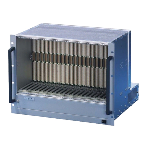
VME64x System Subrack 8 U Product Definition 20836-820 2.1 Mechanical Overview Figure 1: Mechanical Overview 3 .3 + 5 V + 1 2 -1 2 F A N T E M 10006841 VME64x Backplane Fan Tray Front card cage Rear card cage Air filter Power Supply Fan Control Module (FCM) -
Page 10: Subrack
VME64x System Subrack 8 U Product Definition 20836-820 2.2 Subrack The 8 U / 19“ system based on the Schroff europacPro System with EMC shielding. The subrack is equipped with a front card cage for up to 21 VME64x Boards (6 U, 4 HP, 160 mm deep) and a rear card cage for up to 21 Rear I/O Boards (6 U, 4 HP, 80 mm deep). -
Page 11: Power Supply
VME64x System Subrack 8 U Product Definition 20836-820 2.4 Power Supply Hazardous voltage! Parts of the power supply may be exposed with hazardous voltage. Always remove mains/line connector before carry out any assembly work. Caution! Your system has not been provided with a AC power cable. Purchase a AC power cable that is approved for use in your country. - Page 12 VME64x System Subrack 8 U Product Definition 20836-820 Figure 2: Power Supply 10006814 Table 1: Data AC Power Supply Input voltage nominal 100 - 240 VAC Mains Frequency 50 / 60 / 400 Hz Output (max.) 642 W (600 W if U < 200 VAC) Output voltages 12.0 -12.0...
- Page 13 VME64x System Subrack 8 U Product Definition 20836-820 Figure 3: Block Diagram 10006816 www.schroff.biz R1.1, November 14, 2008...
-
Page 14: Thermals
VME64x System Subrack 8 U Product Definition 20836-820 2.5 Thermals The front boards are cooled by forced air convection through 3 speed controlled 24 VDC axial fans (each fan 270 m³/h (160 cfm)). The fans are assembled on a front-accessable Fan Tray below the card cage. The fan speed is controlled by the Fan Control Module (FCM) depending on the exhaust temperature. -
Page 15: Fan Control Module (Fcm)
VME64x System Subrack 8 U Product Definition 20836-820 2.6 Fan Control Module (FCM) The Fan Control Module (FCM): • Monitors and controls up to four fans • Monitors the signals from up to four temperature sensors • Controls the Display Module •... -
Page 16: Chassis Monitoring Module (Cmm) -Optional
VME64x System Subrack 8 U Product Definition 20836-820 2.7 Chassis Monitoring Module (CMM) -optional- The Chassis Monitoring Module (CMM) • monitors the four VME64x voltages • can monitor two additional voltages with a range of ±24 V • can monitor up to seven NTC temperature sensors •... -
Page 17: Display Module
VME64x System Subrack 8 U Product Definition 20836-820 2.8 Display Module Figure 6: Display Module The Display Module is located at the upper front side of the subrack. 4 green LEDs signal the 4 VME64x voltages, two red LEDs signal over-temperature and fan fail events. -
Page 18: Installation
VME64x System Subrack 8 U Installation 20836-820 3 Installation 3.1 Unpacking Caution! When opening the shipping carton, use caution to avoid damaging the system. Consider the following when unpacking and storing the system: • Leave the system packed until it is needed for immediate installation. •... -
Page 19: Rack-Mounting
VME64x System Subrack 8 U Installation 20836-820 3.2 Rack-Mounting Warning! Do NOT move the a full equipped system by yourself. Due to the weight at least two persons are needed to accomplish this task Warning! Do NOT stack the system on top of any other equipment. If the system falls, it can cause severe bodily injury and damage the equipment. -
Page 20: Initial Operation
VME64x System Subrack 8 U Installation 20836-820 3.3 Initial Operation Warning! Voltages over 60 VDC can be present in this equipment. This equipment is intended to be accessed, to be installed and maintained by qualified and trained service personnel only. This eqipment is designed in accordance with protection class 1! It must therefore be operated only with protective GND/earth connection! Before starting the system with VME boards the following tests have to be done:... -
Page 21: Service
VME64x System Subrack 8 U Service 20836-820 4 Service 4.1 Technical support and Return for Service Assistance For all product returns and support issues, please contact your Schroff sales distributor or www.schroff.biz. We recommend that you save the packing material. Shipping without the original packing material might void the warranty. -
Page 22: Scope Of Delivery
VME64x System Subrack 8 U Service 20836-820 4.3 Scope of delivery Quantity Description 19" subrack, shielded, with perforated top and base covers and front handles. (front handles: RAL 9005; 19"-brackets, top and base covers: RAL 9006) VME64x Backplane (VITA 1.1-1997), 21-Slot 6 U Front assembly area for max. -
Page 23: Technical Data
VME64x System Subrack 8 U Technical Data 20836-820 5 Technical Data Table 2: Technical Data Dimensions Height 355 mm (8 U) Width 483 mm (19“) Depth 412 mm Weight 18 Kg Power supply Input voltage 100 VAC to 240 VAC Mains frequency 50 / 60 / 400 Hz Power consumption) - Page 24 VME64x System Subrack 8 U Technical Data 20836-820 www.schroff.biz R1.1, November 14, 2008...
- Page 26 SCHROFF GMBH www.schroff.biz Langenalberstr. 96-100 Tel.: + 49 (0) 7082 794-0 Fax: +49 (0) 7082 794-200 D-75334 Straubenhardt...
Need help?
Do you have a question about the Schroff 20836-820 and is the answer not in the manual?
Questions and answers