
Subscribe to Our Youtube Channel
Related Manuals for MINN KOTA RIPTIDE MAXXUM


Summary of Contents for MINN KOTA RIPTIDE MAXXUM
- Page 1 BowGuard 360° ® Latch & Door RIPTIDE MAXXUM ® ® BOW-MOUNT TROLLING MOTOR USER MANUAL...
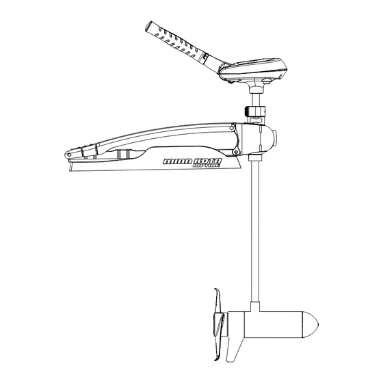
- Page 2 FEATURES Tilt/Extend Tiller Controls: On/Off, Speed, Forward/Reverse and Direction Battery Meter Depth Collar Knob Steering Tension Knob BowGuard 360° ® Breakaway Protection (On Applicable Models) Lifetime Warranty Flexible Composite Shaft Cool Quiet Power Motor Propeller Specifications subject to change without notice. This diagram is for reference only and may differ from your actual motor.
-
Page 3: Mount Installation
MOUNT INSTALLATION TOOLS AND RESOURCES REQUIRED: • (2) 1/2” Wrenches • Standard or Needle Nose Pliers • A second person to help with the installation Upper Pin with Upper Arm Nut and Washer Upper Pin with Upper Arm Nut and Washer Bow Guard Lower Pin Bow Guard... - Page 4 MOUNT INSTALLATION 3. Open upper arm, rotate and lay over out of the way for lower arm assembly. 4. Align the lower arm and the lower bow guard ears and insert lower pin. 5. Re-install spring clip into lower pin for freshwater models or (E-clip for saltwater motors). 6.
- Page 5 (2 on each side) in the bow plate and drill through with a 9/32” drill bit. Either pattern may be used when installing the motor. - Pattern 1: Minn Kota 3” bolt pattern standard motors. - Pattern 2: Alternate 4” bolt pattern commonly used.
- Page 6 MOUNT INSTALLATION INSTALLING THE BOWMOUNT STABILIZER KIT Tools Needed: • Hand Saw • 3/8” Nut Driver • File or Sandpaper 1. Place the motor in the stowed position. 2. Measure from the screw hole in the upper arm to the boat deck or gunwale. Add 3/4”...
-
Page 7: Conductor Gauge And Circuit Breaker Sizing Table
CAUTION: These guidelines apply to general rigging to support your Minn Kota motor. Powering multiple motors or additional electrical devices from the same power circuit may impact the recommended conductor gauge and circuit breaker size. If you are using wire longer than that provided with your unit, follow the conductor gauge and circuit breaker sizing table below. -
Page 8: Selecting The Correct Batteries
• It is highly recommended that a circuit breaker or fuse be used with this trolling motor. Refer to “Conductor Gauge and Circuit Breaker Sizing Table” in the previous section to fi nd the appropriate circuit breaker or fuse for your motor. For motors requiring a 60-amp breaker, the Minn Kota MKR-19 60-amp circuit breaker is recommended. CONNECTING THE BATTERIES 12 VOLT SYSTEMS: 1. -
Page 9: Motor Wiring Diagram
MOTOR WIRING DIAGRAM NOTE: This is a universal, multi-voltage diagram. Double-check your motor's voltage for proper connections. Over-Current Protection Devices not shown in this illustration. VARIABLE SPEED CONTROL BOARD BLACK M- SPEED ADJUSTMENT SWITCH BATTERY GAUGE RED B+ BLACK B- BLACK 12V BATT 1 MOTOR... - Page 10 MOTOR WIRING GUIDE NOTE: This is a universal, multi-voltage diagram. Double-check your motor's voltage for proper connections. Over-Current Protection Devices not shown in this illustration. FIVE-SPEED SWITCH BATTERY METER BLACK RED+ WHITE YELLOW BLACK- RED B+ BLACK B- MOTOR Battery 1 Battery 1 Battery 2...
-
Page 11: Using And Adjusting The Motor
USING AND ADJUSTING THE MOTOR STOWING AND DEPLOYING THE MOTOR WARNING: When raising or lowering the motor, keep fi ngers clear of all hinge and pivot points and all moving parts. MOUNT FEATURES • The motor mount is designed to fold back and lock the motor fl at on the deck when not in use and to provide secure stowage for transport. - Page 12 USING & ADJUSTING THE MOTOR ADJUSTING THE DEPTH OF THE MOTOR Quick Release Depth Collar Lever Arm When setting the depth be sure the top of the motor is submerged at least 12” to avoid churning or agitation of surface water. The propeller must be completely Steering Tension Vertical Stow Knob submerged.
- Page 13 USING & ADJUSTING THE MOTOR CONTROLLING SPEED & STEERING WITH THE TILLER This motor off ers variable forward and reverse speeds. The speed control may be operated in either direction, forward or reverse. Turn the tiller handle counterclockwise from (OFF) to increase reverse speed and clockwise from (OFF) to increase forward speed.
-
Page 14: Propeller Replacement
SERVICE & MAINTENANCE PROPELLER REPLACEMENT Propeller TOOLS AND RESOURCES REQUIRED: • Box End Wrench - 1/2” for motors with 70 lbs thrust or lower. - 9/16” for motors with 80 lbs thrust or higher. • Screwdriver (optional) Anode/Nut Washer CAUTION: Disconnect the motor from the battery before beginning any prop work or maintenance. - Page 15 TROUBLESHOOTING & REPAIR 1. Motor fails to run or lacks power: • Check battery connections for proper polarity. • Make sure terminals are clean and corrosion free. Use fi ne sandpaper or emery cloth to clean terminals. • Check battery water level. Add water if needed. 2.
-
Page 16: Compliance Statements
Minn Kota motors are not subject to the disposal regulations EAG-VO (electric devices directive) that implements the WEEE directive. Nevertheless never dispose of your Minn Kota motor in a garbage bin but at the proper place of collection of your local town council. -
Page 17: Parts Diagram
RIPTIDE MAXXUM 55/SC LATCH & DOOR 55 LBS THRUST - 12 VOLT - 42”/52” SHAFT This page provides Minn Kota® WEEE compliance disassembly instructions. For more information about where you should dispose of your waste equipment for recycling and recovery and/or your European Union member state require- ments, please contact your dealer or distributor from which your product was purchased. -
Page 18: Parts List
PARTS LIST RIPTIDE MAXXUM 55/SC LATCH & DOOR 55 LBS THRUST - 12 VOLT - 42”/52” SHAFT PART PART ITEM DESCRIPTION ITEM DESCRIPTION NUMBER NUMBER 2097097 12V MOTOR SW 2063405 SCREW, #6 PFH SS 2-100-121 ARMATURE ASSEMBLY 2884091 YOKE / SPIDER ASSY, 5SPD... - Page 19 Stop buying new batteries and start taking care of the ones you’ve got. Many chargers can actually damage your battery over time – creating shorter run times and shorter overall life. Digitally controlled Minn Kota chargers are designed to provide the fastest charge that protect and extend battery life.
Need help?
Do you have a question about the RIPTIDE MAXXUM and is the answer not in the manual?
Questions and answers