Table of Contents
Advertisement
Quick Links
801 Avenida Acaso, Camarillo, Ca. 93012 • (805) 494-0622 •
www.sdcsecurity.com • E-mail: service@sdcsecurity.com
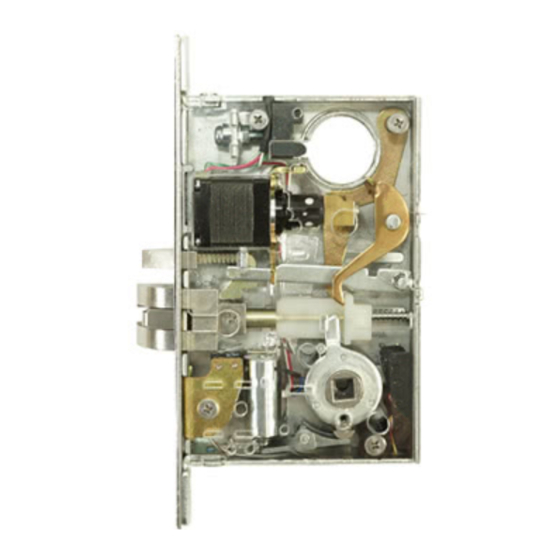
Z7700 SERIES MOTORIZED RETRACTION x ELECTRIC SOLENOID
A. Door Preparation:
1. Measure desired height from finished floor, mark a horizontal line on door and door edge.
2. Align template on edge of door with applicable horizontal at height line. Check the chart for drilling trim
holes on template and mark only holes for lock function being installed.
Height line
C L
of lever
or knob
3. Mortise door edge according to measurements on
installation template and drill proper holes for trim.
4. Recess for face plate, the dimension is:
L 8-1/32" x W 1-5/16" x D 7/32".
5. Route wiring through door as required. Reference
wiring section on Page 4
7/32"
P:\INSTALLATION INST\Electrified Lockset\INST-Z7700
INSTALLATION INSTRUCTIONS
MORTISE LOCK SET
C
L of
door edge
Installation
template
C L
of cylinder
of lockcase
C L
C L
of lever
Vertical centerline
B. Strike Installation:
4-7/8"
3-17/32"
REV
09-19
Page 1
NOTCH OPENING FOR MOTOR
*
ON WOOD DOORS ONLY
3/8"
2-1/4"
1-1/2"
(1-3/4" DEEP)
or knob
3/8"
1. Align strike template on jamb.
Be sure to keep 3/8" distance
between lock centerline and
C L
Jamb
strike centerline. Recess
5/32" for flush fit of strike and
dust box.
1" Holes
1-1/8" Deep
2. Mortise jamb according to
measurement of strike template.
Then fit strike and dust box into
C L
Strike
3/8"
Lock C L
frame and secure into place with
supplied screws.
3/8"
Any suggestions or comments to this instruction or
product are welcome. Please contact us through
our website or email engineer@sdcsecurity.com
1-1/4"
(1-3/4" DEEP)
2X 12-24 WMS
5-5/8"
WOOD
*
DOOR
1" hole
4-3/4" DEEP
Advertisement
Table of Contents

Subscribe to Our Youtube Channel
Related Manuals for SDC Z7700 Series


Summary of Contents for SDC Z7700 Series
- Page 1 801 Avenida Acaso, Camarillo, Ca. 93012 • (805) 494-0622 • www.sdcsecurity.com • E-mail: service@sdcsecurity.com INSTALLATION INSTRUCTIONS Z7700 SERIES MOTORIZED RETRACTION x ELECTRIC SOLENOID MORTISE LOCK SET A. Door Preparation: 1. Measure desired height from finished floor, mark a horizontal line on door and door edge.
- Page 2 C. Install Lockcase Instructions for changing lock hand: 1. Change latchbolt handing: If the hand of the latchbolt doesn’t match the door hand, remove the fixing screw and pull the latchbolt out from Remove screw Pull out and turn lock case. Turn the latchbolt 180° to change the handling.
- Page 3 E. Install Lever trim (continued) 6. Screw inside lever into position and tighten lever collar with supplied spanner wrench. spanner wrench. Spanner wrench F. Install Cylinder and Armor Face Plate 1. Screw cylinder into threaded hole of lock case. USE THIS CAM. 2.
- Page 4 G. Lock Wiring External Control Board SDC P/N 631RF is recommended. LEVER LATCH 24VDC Regulated & Filtered Power 24VDC (Continuous) Supply (1.5A min) Solenoid Activation Switch (Dry, N/O) Motor Activation Switch (Dry, N/O) Power & Controls FIELD WIRING: 6 COND MINIMUM...
- Page 5 Make sure the lock hand matches the door hand, use the following diagram to determine the hand of door. INSIDE OF DOOR Right Hand Left Hand OUTSIDE OF DOOR INSIDE OF DOOR RHRB LHRB Right Hand Left Hand Reverse Bevel Reverse Bevel OUTSIDE OF DOOR OPTIONAL...
Need help?
Do you have a question about the Z7700 Series and is the answer not in the manual?
Questions and answers