Advertisement
Quick Links
3580 Willow Lane, Westlake Village, CA 91361-4921 • (805) 494-0622 • Fax: (805) 494-8861
www.sdcsecurity.com • E-mail: service@sdcsecurity.com
IMPORTANT: THIS LOCK IS NON-HANDED. LOCK IS
FACTORY PACKED PREADJUSTED FOR 1-3/4" (45MM)
THICK DOORS. TO ADJUST LOCK FOR OTHER DOOR
THICKNESS, SEE STEPS 8, 9 & 10. SPACERS MUST
BE USED FOR DOORS THINNER THAN 1-3/4" (45MM)
THICK.
STEP 1
MARK DOOR
Fold template on line indicated.
Place on HIGH EDGE of door bevel.
Position centerline of template on heightline
(suggested height is 38" (965mm) from floor.)
A.
Locate and mark center for 2-1/8" (54mm) hole.
B.
Locate and mark positions for notches.
Caution: Notches must be horizontal.
C. Locate and mark center for two (2) 5/16" (8mm)
thru-bolt holes.
D. Locate and mark center for 1" (25mm) latch bolt hole
in door edge.
Note: If steel frames are used, the latch centerline must
be in line with the center of the strike preparation.
Hint: For retrofitting of existing 2-1/8" (54mm) holes, fold template in half to locate position for the two (2) 5/16" (8mm) holes.
M:\INS\INST-ZA7200
0200
Page 1
SECURI T Y DO O R CO NT RO LS
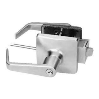
ZA7200 SERIES HITOWER CYLINDRICAL LOCK
INSTALLATION INSTRUCTIONS
Advertisement

Subscribe to Our Youtube Channel
Related Manuals for SDC ZA7200 Series


Summary of Contents for SDC ZA7200 Series
- Page 1 SECURI T Y DO O R CO NT RO LS 3580 Willow Lane, Westlake Village, CA 91361-4921 • (805) 494-0622 • Fax: (805) 494-8861 www.sdcsecurity.com • E-mail: service@sdcsecurity.com ZA7200 SERIES HITOWER CYLINDRICAL LOCK INSTALLATION INSTRUCTIONS IMPORTANT: THIS LOCK IS NON-HANDED. LOCK IS FACTORY PACKED PREADJUSTED FOR 1-3/4”...
- Page 2 STEP 2 BORE HOLES - INSTALL LATCH When drilling through door, be careful not to damage door finish. Bore a 2-1/8” (54mm) hole and two (2) 5/16” (8mm) holes from both sides of door to avoid splintering wood. Bore a 1” (25mm) hole into door edge. Using latch faceplate as pattern, trace outline and mortise door edge so latch is flush with door.
- Page 3 STEP 5 INSTALL INNER TRIM ASSEMBLY Slide inner trim assembly over chassis spindle. Thru-posts will engage inner trim assembly on 1-3/4” (45mm) thick doors. Secure to door with two (2) #10-32 x 1” machine screws provided. STEP 6 INSTALL INNER LEVER Position rose over inner trim assembly making sure rose detent engages groove in spindle assembly.
- Page 4 STEP 9 ADJUST LOCK FOR DOOR THICKNESS Lock is factory packed preadjusted for 1-34” (45mm) doors unless ordered special. Place template provided against retractor housing to find marking for door thickness. If adjustment is necessary, use black hex wrench provided and rotate flanged nut counterclockwise to adjust.
- Page 5 STEP 13 TO REMOVE ALL CYLINDER LEVERS (Except Interchangeable Core) Insert key and rotate clockwise approximately 60 degrees. Depress lever retainer with tool provided. Slide lever off spindle. TO RE-INSTALL LEVER Insert cylinder into spindle. Slide lever onto spindle. Insert key into cylinder and rotate clockwise approximately 60 degrees and push lever over retainer.
- Page 6 STEP 17 TIMING INSTRUCTIONS FOR STANDARD CYLINDER LOCKS If the cylinder and handle are installed, refer to Step 13 for lever removal instructions. Using a thin flat screwdriver, turn the action bar slot clockwise (cw) until it stops at about 2:00. Then turn the action bar counterclockwise (ccw) to the 9:00 position.
-
Page 7: Wiring Diagram
WIRING DIAGRAM MODEL #ZA7250 FUNCTION: #ZU7350 Fail-Safe power to lock. Locked outside, free egress from inside. Lock is unlocked by access control, remote switch, or means of outside key or by rotating inside lever. MODEL #ZA7260 FUNCTION: #ZU7360 Fail-Secure power to unlock. Locked outside, free egress from inside. - Page 8 AWG WIRE CHART To determine the correct wire gauge to use on “one circuit” the following information is required: 1. The quantity, voltage, and current draw of all lock(s) to be used. 2. The distance in feet from the power supply to the furthest lock. Add together the current draw (amps) of all locks on the same circuit.
- Page 9 SECURI T Y DO O R CO NT RO LS 3580 Willow Lane, Westlake Village, CA 91361-4921 • (805) 494-0622 • Fax: (805) 494-8861 www.sdcsecurity.com • E-mail: service@sdcsecurity.com ZU7300 SERIES HITOWER UNIT LOCK INSTALLATION INSTRUCTIONS IMPORTANT: THIS LOCK IS NON-HANDED. LOCK IS FACTORY PACKED PREADJUSTED FOR 1-3/4”...
- Page 10 STEP 2 MARK DOOR Fold template on lines indicated. Place on HIGH EDGE of door bevel. Place template on high edge of door bevel. Center the template to the slot opening and mark 2-1/8” diameter on surface of door. Repeat same for low edge of door.
- Page 11 STEP 6 INSTALL INNER TRIM ASSEMBLY Position inner trim assembly with arrow towards door edge and slide onto chassis spindle. Thru-posts will engage inner trim assembly. Secure to door with the two (2) #10-32 x 1” screws provided. STEP 7 INSTALL INNER LEVER Position rose over inner trim assembly.
- Page 12 STEP 9 INSTRUCTIONS FOR REHANDING LOCK FOR DOOR BEVEL Temporarily, re-install latch assembly mounting screws (A) on the inside without the inside mounting plate (this is to hold the support plates in place during rehanding). Remove the outside trim retaining screw (B). Slide the outside trim (C) from the chassis assembly.
- Page 13 STEP 12 TO REMOVE STANDARD CYLINDER LEVERS Insert key and rotate clockwise approximately 60 degrees. Depress lever retainer with tool provided. Slide lever off spindle. TO RE-INSTALL LEVER Insert cylinder into spindle. Slide lever onto spindle. Insert key into cylinder and rotate clockwise approximately 60 degrees and push lever over retainer.
- Page 14 STEP 15 TIMING INSTRUCTION FOR IC CYLINDER LOCKS If the core is installed, refer to Step 10 for IC core removal instructions. Using a thin flat screwdriver, turn the action bar slot clockwise (cw) until it stops at about 11:00. Then turn the action bar counterclockwise (ccw) to the 7:00 position.
- Page 15 WIRING DIAGRAM MODEL #ZA7250 FUNCTION: #ZU7350 Fail-Safe power to lock. Locked outside, free egress from inside. Lock is unlocked by access control, remote switch, or means of outside key or by rotating inside lever. MODEL #ZA7260 FUNCTION: #ZU7360 Fail-Secure power to unlock. Locked outside, free egress from inside.
- Page 16 AWG WIRE CHART To determine the correct wire gauge to use on “one circuit” the following information is required: 1. The quantity, voltage, and current draw of all lock(s) to be used. 2. The distance in feet from the power supply to the furthest lock. Add together the current draw (amps) of all locks on the same circuit.
- Page 17 SECURITY DOOR CONTROLS 3580 Willow Lane, Westlake Village, CA 91361-4921 • (805) 494-0622 • Fax: (805) 494-8861 www.sdcsecurity.com • E-mail: service@sdcsecurity.com ZU7300 SERIES ORDER DETAIL FORM MODEL LEVER TRIM FINISH HAND STRIKE LATCH THROW OPTIONS ZU7350 ZUST1 REX/PTH-4 When evaluating the retrofit requirements for the ZU7300 Series Unit Lock, the following questions need to be addressed: 1.
- Page 18 ” backset. Also available for 2” and 2 ” thick doors. Please specify. 5. Specify cylinder requirements. Note: Locks furnished with SDC 6-pin standard Schlage C keyway cylinder or prepared for SDC interchangeable core unless otherwise specified. With Cylinder Less Cylinder - Prepared to Accept**...
Need help?
Do you have a question about the ZA7200 Series and is the answer not in the manual?
Questions and answers