Table of Contents
Advertisement
Quick Links
IMPORTANT: RECEIVING INSTRUCTIONS
Visually inspect all components for shipping damage. If you find damage, notify the carrier at once.
Shipping damage is NOT covered by warranty. The carrier is responsible for all repair or replacement costs resulting from damage in shipment.
Read this owners manual thoroughly before use and save.
1
2
3
4
Rotary Switch
OFF
Power off
AC Voltage Measurement
DC Voltage Measurement
6
5
A
400A
A
400A
Autorange
A
400A
1 . 8 . 8 . 8
A
400A
7
8
AC
9
DC
10
Figure 2
9
8
7
5
6
Resistance Measurement
Continuity Measurement
AC/DC Current Measurement
A
400A
Autorange
1 . 8 . 8 . 8
A
400A
4
3
2
1
AC
MAX MIN
DC
AC
DC
OPERATING INSTRUCTIONS
Thin Autoranging Multimeter
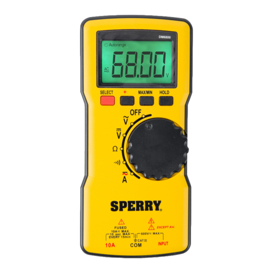
1.0 DISPLAY FUNCTIONS & SYMBOLS
1.1 FUNCTIONS (Figure 1)
1. Display: Backlit 1999 Count LCD screen
2. SELECT Button: Press to switch between DC current
and AC current measurement functions.
3. BACKLIGHT Button: Press to turn on the backlight. Press again to turn off the
backlight. The backlight will automatically turn off 30 seconds after it is turned on.
4. 10A Terminal: Red test lead input jack for current measurements.
5. COM Terminal: Black test lead input jack common to all measurements.
6. INPUT Terminal: Red test lead input jack for all measurements
expect current measurements.
7. Rotary Switch: Turn to power the meter on and off and select the desired
measurement function. To save battery power, turn to the "OFF" position when
the meter is not in use. See "ROTARY SWITCH" section for function descriptions.
8. MAX/MIN Button: Press to enter or exit the Min/Max recording mode.
9. HOLD Button: Press to enter or exit the Data Hold mode.
1.1 METER FUNCTIONS
Meter type:
Display Count:
Sampling Rate:
Battery:
Input impedance:
AC Volt Ranges:
DC Volt Ranges:
AC Amps:
DC Amps:
Resistance Ranges:
Over Range Indication:
Polarity Indication:
Overload Protection:
Agency Approvals:
Operating Temperature: 32°F–104°F (0°C–40°C)
Relative Humidity:
Storage Temperature:
IP Degree:
Dimension:
Weight:
Altitude:
Warranty Info:
1.2 DISPLAY SYMBOLS (Figure 2)
MAX MIN
1.
: The battery is low and must be replaced immediately
2. MIN: Minimum reading is being displayed.
3. MAX: Maximum reading is being displayed
Autorange
MAX MIN
4.
: Continuity test is selected
1 . 8 . 8 . 8
5. AUTORANGE: Autorange mode is selected.
Autorange
1 . 8 . 8 . 8
Autorange
Autorange
6.
: Automatic power-off feature is enabled
1 . 8 . 8 . 8
1 . 8 . 8 . 8
Autorange
Autorange
1 . 8 . 8 . 8
1 . 8 . 8 . 8
7.
: Data Hold is enabled
AC
8.
: Negative sign
AC
AC
DC
AC
9.
: AC
AC
DC
DC
DC
DC : DC
10.
1
DM6800
Auto
1999
About 2 to 3 times/sec
Requires 2 AAA batteries
10 Meg Ohm
2V, 20V, 200V, 600V, best accuracy (1.0%+5)
200mV, 2V, 20V, 200V and 600V, best accuracy (0.8%+5)
2A, 10A, best accuracy (1.5%+5)
2A, 10A, best accuracy (1.2%+5)
200ohm, 2kohm, 20kohm, 200kohm, 2M ohm
and 20M ohm, best accuracy (1.0%+5)
Displayed value > 1999 or the input
measurement range, displays OL
"-" is displayed for negative polarity
10A/600V Fast fuse
ETL, CE (IEC/EN61010:, CAT III 600V, Pollution Degree 2)
< 85%
-4°F–140°F (-20°- 60°C)
IP20
176mm x 81mm x 17mm
Around 180g (without batteries)
Maximum 2000m
Limited lifetime warranty
MAX MIN
MAX MIN
MAX MIN
MAX MIN
MAX MIN
Advertisement
Table of Contents

Related Manuals for Sperry instruments DM6800


Summary of Contents for Sperry instruments DM6800
- Page 1 OPERATING INSTRUCTIONS Thin Autoranging Multimeter DM6800 IMPORTANT: RECEIVING INSTRUCTIONS Visually inspect all components for shipping damage. If you find damage, notify the carrier at once. Shipping damage is NOT covered by warranty. The carrier is responsible for all repair or replacement costs resulting from damage in shipment.
- Page 2 2.0 READ FIRST: IMPORTANT SAFETY INFORMATION Read this operators manual thoroughly before using this multimeter. This manual is intended to provide basic information regarding this meter and to describe common test procedures which can be made with this unit. Many types of appliance, machinery and other electrical circuit measurements are not addressed in this manual and should be handled by experienced service technicians.
- Page 3 Measurement categories (Over-voltage categories) To ensure safe operation of measuring instruments, IEC61010 establishes safety standards for various electrical environments, specified as CAT I through CAT IV, and called measurement categories. Higher-numbered categories correspond to electrical environments with greater momentary energy, so a measuring instrument designed for CAT III environments can endure greater momentary energy than one designed for CAT II.
- Page 4 4.0 FUNCTIONS 4.1 MAX/MIN BUTTON 1. Press MAX/MIN once to enter MAX mode. The symbol “MAX” will appear on the display and the display will show the maximum reading that the meter measures while in this mode. 2. Press MAX/MIN again to enter MIN mode. The symbol “MIN” will appear on the display and the display will show the minimum reading that the meter measures while in this mode.
- Page 5 400A 5.4 DC AMPS If the fuse burns out during measurement, the meter may be damaged or personal injury may occur. To avoid possible damage to the 400A meter or to the equipment under test, check the meter’s fuses before measuring current. Use the proper terminals, function, and range for the measurement.
- Page 6 Test leads, fuses, batteries and calibration are not covered under any implied warranty. “Lifetime” of products that are no longer offered by Sperry will be either repaired or replaced with an item of Sperry Instruments choice of similar value. Lifetime is defined as 5 years after Sperry discontinued manufacturing the product, but the warranty period shall be at least ten years from date of purchase.
Need help?
Do you have a question about the DM6800 and is the answer not in the manual?
Questions and answers