
Subscribe to Our Youtube Channel
Related Manuals for Sperry instruments SP-5A


Summary of Contents for Sperry instruments SP-5A
- Page 1 Form # 146-2 OPERATING INSTRUCTIONS MODEL SP-5A 13 Range Analog Multimeter ® ® Shown 1/2 Actual size A.W. SPERRY INSTRUMENTS INC. 245 MARCUS BLVD., HAUPPAUGE, N.Y. 11788...
-
Page 2: Table Of Contents
Instruments, Inc. Attention: Customer Service Center, 245 Marcus Boulevard, Hauppauge, New York 11788, postage prepaid for examination and verification of manufacturing defect under warranty. A.W. Sperry Instruments, Inc. shall be limited to the repair or replacement at its sole option of any defective product. - Page 3 If you should have any questions regarding this product or would like a catalog on our other products please write to us at: A.W. Sperry Instruments, Inc. P.O. Box 9300 Smithtown, N.Y. 11787 Or call us Toll-Free at 800-645-5398 (N.Y., Hawaii, Alaska call collect...
-
Page 4: Description
Don’t become part of the circuit. Think Safety. Act Safely. 3) INSTRUMENT DATA 3-1) Description The AWS SP-5A is an Analog Multimeter capable of measuring 5 functions on 13 ranges. A mirror scale is provided to reduce the possibility of paralex errors. Small lightweight and rugged construction. -
Page 5: Packaging
Size: 1-3/16” D x 2-3/8” W x 3-1/2” H Weight: 3.7 oz. (including battery) Operating Environment: 0° to 50°C (32° to 122° F) Max RH 80% at 31° C decreasing linearly to 50% RH at 40° C. Instrument complies with installation category (over voltage category II). -
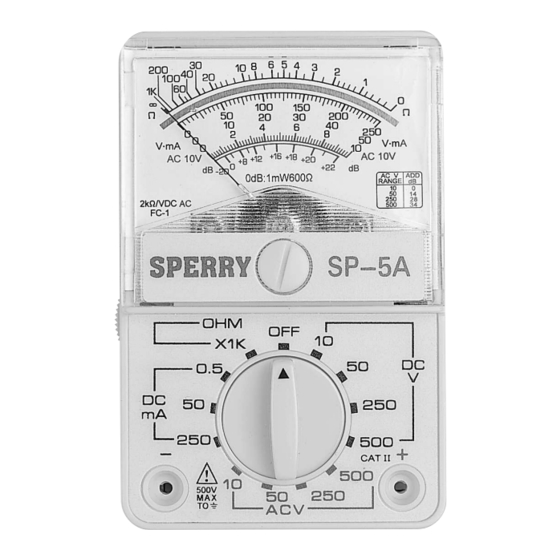
Page 6: Front Panel Identification
3-5) Front Panel Identification... - Page 7 “0” reading on the left side of the scale plate. 5) Insert the black test led into the “-” terminal of the SP-5A and the red test lead into the “+” terminal. Make certain that the leads are...
- Page 8 6-1. Note: The SP-5A is now ready for use. Follow measurements with the selector switch in the “ X1K” position. The SP-5A can be used in all other ranges with a weak, dead or missing battery. 7) The SP-5A is now ready for use. Follow the Measurement pro- cedures in this manual for all measurements.
-
Page 9: Current Measurement
take a measurement. 4) Apply the test leads to the two points in the circuit at which the voltage is to be measured. When measuring DC voltage the black lead should be connected to the more negative point of measure- ment. -
Page 10: Resistance Measurement
the equipment under test. 3) Select the mAdc range that is higher than the maximum current to be measured. If the maximum current is unknown, do not attempt to take a measurement. 4) Remove power from the circuit to be tested and discharge any capacitors and inductors. -
Page 11: Battery Replacement
Be certain equipment is completely de-energized. 3) Set the selector switch to: X1K” position. Hold the test lead tips together and adjust for a “0” OHM reading using the “OHM Zero Adjust” knob. If a zero reading cannot be obtained a weak battery is the most probable cause. -
Page 12: Fuse Replacement
25 PSI. 7) RETURN FOR REPAIR Before returning your SP-5A Analog Multimeter for repair be certain that the failure to operate is not cause by a: 1) Weak battery.
Need help?
Do you have a question about the SP-5A and is the answer not in the manual?
Questions and answers
What year did A W Sperry manufacture this model multimeter