Table of Contents
Advertisement
04/06
PLEASE READ THESE OPERATING INSTRUCTIONS CAREFULY
Misuse and abuse of these instruments cannot be prevented by any
printed word and may cause injury and or equipment damage. Please
follow all these instructions and measurement procedures faithfully and
adhere to all standard industry safety rules and practices.
The Professional's Choice
OPERATING INSTRUCTIONS
Model DM-4400A
DIGITAL MULTIMETER
®
2150 Joshua's Path, Suite 302
Hauppauge, New York 11788
1-800-645-5398 | 631-231-7050
Fax: 631-434-3128
Form # 415
Advertisement
Table of Contents

Subscribe to Our Youtube Channel
Related Manuals for Sperry instruments DM-4400A


Summary of Contents for Sperry instruments DM-4400A
- Page 1 04/06 Form # 415 OPERATING INSTRUCTIONS Model DM-4400A DIGITAL MULTIMETER PLEASE READ THESE OPERATING INSTRUCTIONS CAREFULY Misuse and abuse of these instruments cannot be prevented by any printed word and may cause injury and or equipment damage. Please follow all these instructions and measurement procedures faithfully and adhere to all standard industry safety rules and practices.
-
Page 2: Table Of Contents
CONTENTS SECTION TITLE PAGE Warranty Description Features Specifications Safety Rules Front Panel Controls Preparation for Use Unpacking and Contents Check Pre-Operation Procedure Battery Replacement Fuse Replacement Operation Voltage Measurements Current Measurements 12-13 Resistance Measurements Battery Test Measurements Diode Tests Non Contact Voltage (NCV) Tests Maintenance 10.1 Cleaning... -
Page 3: Warranty
11788, postage prepaid for examination and verification of manufacturing defect under warranty. Sperry Instruments, Inc., shall be the sole judge of such defect. The liability of Sperry Instruments, Inc., shall be limited to the repair or replacement at its sole option of any defective product. -
Page 4: Description
DESCRIPTION Sec. 1 This exceptional 3-1/2 digit handheld, digital multimeter has the capacity of reading up to 6 functions on up to 18 ranges. This DMM offers a powerhouse of measurement capability in a small self-contained housing. It is designed for the professional at work, in the field or in the laboratory. - Page 5 Storage Environment: -20° C to 60° C (-4 F to 140° F) at 80% relative humidity. Power Source: One (1) 9V Transistor Type Battery. (NEDA #1604). Power Consumption: 30mW typical Battery Life: 1000 hours typical with zinc carbon. Battery Indicator: "...
- Page 6 DC Current Range Resolution Accuracy (18°C to 28°C) Full Scale Burden Voltage 1µA ±(1.0% of rdg + 4d) 0.25V 200mA 100µA " " 10mA ±(3.0% of rdg + 1d) 1.2V Overload Protection: 0.5A/250V fuse on mA inputs 10A for 60 seconds on 10A input (unfused) AC Current Range Resolution...
-
Page 7: Safety Rules
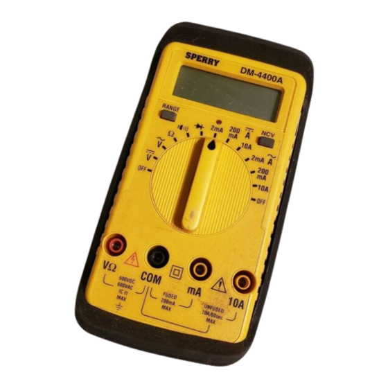
10. Do not install substitute parts or perform any unauthorized modification of the instrument. Return the instrument to Sperry Instruments for service and repair to insure that safety features are maintained. 11. To avoid electric shock use CAUTION when working with voltages above 40Vdc or 20Vac. - Page 8 NCV Sensor End Digital Display Non Contact Voltage Function Range Selector Switch Input Terminals Fig. 1...
-
Page 9: Front Panel Controls
Sec. 6 UNPACKING AND CONTENTS CHECK Sec. 6.1 The DM-4400A comes complete and ready to use. Check the following contents list when unpacking. If any pieces are missing notify the distributor you purchased the instrument from or Sperry Instrument, Inc. -
Page 10: Battery Replacement
7. If any abnormal conditions exist, do not attempt to take any electrical measurements. Instead refer to sec. 14 Return for Repairs. BATTERY REPLACEMENT Sec. 7 The DM-4400A has a self-contained power supply consisting of One 9V Transistor Type Battery (NEDA #1604). - Page 11 WARNING Before attempting to replace the battery, first disconnect the test leads from any energized circuit and then disconnect the test leads from the instrument. 1. Disconnect the test leads from any energized circuit and then from the instrument. 2. Turn the range switch to the "OFF" position 3.
-
Page 12: Fuse Replacement
FUSE REPLACEMENT Sec. 8 A 0.5A, 250V, 5 x 20mm fast acting fuse, Part # F-17 is installed in the instru- ment and used to protect the ampere ranges (other than the 10A range) along with other solid state components. WARNING Before attempting to replace the fuse, disconnect the test leads from any energized circuit and then disconnect the test leads from the instrument. -
Page 13: Operation
OPERATION Sec. 9 Before making any measurements always examine the instrument and acces- sories used with the instrument for damage, contamination (excessive dirt, grease, etc.) and defects. Examine the test leads for cracked or frayed insula- tion and make sure the lead plugs fit snugly into the instrument jacks. If any abnormal conditions exist do not attempt to make any measurements. -
Page 14: Current Measurements
CURRENT MEASUREMENTS Sec. 9.2 1. Insert the black and red test leads into the respective "COM" and "10A" terminals. 2. Place the function switch to the 10A position. Always start with the highest range of the function to be measured. CAUTION The 10A range is unprotected and has a very low internal resistance. -
Page 15: Resistance Measurements
3. Raise the "COM" terminal potential above 500V to ground. 4. Energize the circuit. If the reading is within the next lower range, switch to that range after completely de-energizing the circuit under test. Continue changing to lower ranges if the reading is within the next lowest range to obtain the best accuracy. -
Page 16: Non Contact Voltage (Ncv) Tests
4. Touch probes to the diodes. A forward-voltage drop is about 0.6V (typical for a silicon diode). 5. Reverse probes. If the diode is good, "1.XXX" is displayed. If the diode is shorted, ".000" or another number is displayed. 6. If the diode is open, "1.XXX" is displayed in both directions. 7. -
Page 17: Maintenance
CALIBRATION Sec. 11 Calibration on these meters should be performed every year. This can be done by sending the instruments prepaid to: Sperry Instruments, Inc. Customer Service Center 2150 Joshua’s Path, Suite 302 Hauppauge, New York 11788 Specify in writing that calibration is necessary. The instrument will be returned... - Page 18 CAUTION The following procedure should be performed by persons trained and qualified in electronics and electronic equipment service. DO NOT attempt this procedure if not qualified. WARNING Do not attempt calibration or service unless another person, capable of rendering first aid and resuscitation is present. Fig.
-
Page 19: Calibration Procedure
CALIBRATION PROCEDURE Sec. 11.1 The procedure should be performed at an ambient temperature of 25°C ± 2°C and at a relative humidity of less than 80%. Allow the instrument to stabilize at this temperature for a minimum of 30 min- utes. -
Page 20: Diagrams
DIAGRAMS Sec. 12 CIRCUIT DIAGRAM Sec. 12.1 Note: Subsequent revisions to this document may exist. Use for general references only. -
Page 21: Parts List
PARTS LIST Sec. 12.2 Part Description Size 40KHz 40KHz XTAL R001 R002 1/4 W C R003 100J* R004 100F 1/4 W C R005 10KJ* R010 160D R011 1.6KD R012 16KD RO13 160KD R014 1.6MD R015 5.9MF R015X 10MF R016, R44, R92 100KJ X3 R021A, B, C, D, E 2MF X5...
Need help?
Do you have a question about the DM-4400A and is the answer not in the manual?
Questions and answers