Advertisement
Quick Links
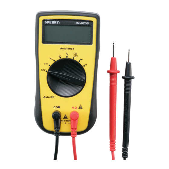
SPERRY
INSTRUMENTS
7 Function, Auto Range
Digital Multi-Meter
• Read this owners manual thoroughly before use and save.
SPERRY
INSTRUMENTS
The Professional's Choice®
Milwaukee, WI 53209
1-800-645-5398
www.sperryinstruments.com
1. 3/12 digit Auto Backlit LCD display
2. Durable drop resistant housing
3. 8 position rotary dial
3132409
4. AC Volts
CONFORMS TO UL 1436
CERTIFIED TO CAN/CSA-C22.2
5. DC Volts
No. 160-M1985
6. Battery test
7. Resistance
8. Diode Test
9. Audible Continuity Test
10. Temperature
11. Common input jack
10
12. Positive input jack
7
1.0 METER FUNCTIONS
6
4
Meter type:
Functions:
Ranges:
5
Display Count:
8
Input impedance:
AC Volt Ranges:
DC Volt Ranges:
Resistance Ranges:
9
Diode Test
Continuity:
Temperature:
(For Temperatures above 446F a rod style temp probe is required)
Battery Test Ranges: 1.5 V (.5% + 2)
Auto Off:
Battery type:
Battery Life:
Over Range Indication: Displayed value > 1999, displays OL (The
11
12
Polarity Indication:
Electro-Magnetic :
When it is under 1V/m frequency : total accuracy = assigned accuracy +5% of the range.
When it is over 1V/m frequency: there is no assigned accuracy.
Agency Approvals:
ETL, CE (IEC/EN61010:, CAT III 600V, Pollution Degree 2
Operating Temperature:
32°F - 104°F (0°C_40°C)
Relative Humidity:
32°F - 86°F below <75%, 86°F - 104°F<50%
Storage Temperature:
14°F - 122°F(-10°C - 50°C)
Dimension:
70mmx137mmx35mm
Weight:
Around 200g (including battery)
Altitude:
Maximum 2000m
Warranty info:
5 yr.
2.0 READ FIRST: IMPORTANT SAFETY INFORMATION
Read this operators manual thoroughly before using this multimeter. This manual is intended to provide basic information
regarding this meter and to describe common test procedures which can be made with this unit. Many types of appliance,
machinery and other electrical circuit measurements are not addressed in this manual and should be handled by experienced
service technicians.
Use extreme caution when using this multimeter. Improper use of this meter can result in severe damage, personal injury or
death. Follow all instructions and suggestions in this operators manual as well as observing normal electrical safety precautions.
Do not use this meter if you are unfamiliar with electrical circuits and proper test procedures.
2.1 FOR YOUR SAFETY
1. Use extreme caution when checking electrical circuits.
2. Do not stand in wet or damp work areas when working with electricity. Wear rubber soled boots or shoes.
3. Do not apply more voltage or current than the set range of the multimeter will allow!
4. Do not touch the metal probes of the test leads when making a measurement.
5. Replace worn test leads. Do not use test leads with broken or tattered insulation.
SPERRY
INSTRUMENTS
7 funciones, rango automático
Multímetro digital
Lea completamente este manual del propietario antes del uso y consérvelo
•
para referencia futura.
1. Pantalla de cristal líquido de 0.65cm dígitos con iluminación
posterior automática
2. Alojamiento durable, resistente a las caídas
10
3. Dial giratorio de 8 posiciones
4. Voltios de CA
7
5. Voltios de CC
6. Prueba de batería
6
4
7. Resistencia
8. Prueba de diodo
5
8
9. Prueba de continuidad audible
10. Temperatura
11. Toma de entrada común
9
12. Toma de entrada positiva
Tipo de medidor:
Rango automático
Funciones:
7
Rangos:
Automáticos
Cuenta en pantalla:
2000
Impedancia de entrada:
10 Meg Ohmios
Rangos de voltios de CA:
0.2 / 2 / 20 / 200 / 500 (0.8% + 5 dígitos)
Rangos de voltios de CC:
0.2 / 2 / 20 / 200 / 500 (0.5% + 5 dígitos)
Rangos de resistencia:
200 / 2k / 200k / 2M / 20M (1% + 2 dígitos)
11
12
Prueba de diodo
Continuidad:
Pitido audible
Temperatura:
4.4°C-400°C*(8%+5)
(Para temperaturas sobre 230°C se requiere una sonda de temperatura estilo vara)
Rangos de prueba de batería:1.5 V (.5% + 2)
Apagado automático:
15 minutos
Tipo de batería:
Dos AAA (incluidas)
Duración de la batería:
100 horas con pilas de carbono-cinc, 200 horas con pilas alcalinas
bajo condiciones normales.
Indicación de sobre rango: Valor mostrado > 1999, muestra OL (La seguridad y precisión solamente se garantizará
dentro del rango de la especificación) por la entrada.
Indicación de polaridad: Aparece "-" para la polaridad negativa
Electro-Magnético :
Cuando está bajo frecuencia de 1V/m : precisión total = precisión asignada +5% del rango.
Cuando está sobre una frecuencia de 1V/m: no hay precisión asignada.
Aprobaciones de agencias:ETL, CE (IEC/EN61010:, CAT III 600V, El grado de la contaminación 2
Temperatura operativa:
0°C - 40°C
Humedad relativa:
32°F - 86°F bajo <75%, 86°C - 104°F<50%
Temperatura de almacenamiento: -10°C - 50°C
DM6250
Replace damaged test leads with identical model number or electrical specifications before using the Meter.
6. Before carrying out any measurement, make sure the display is normal after you turn on the meter.
7. Before using to check hazardous voltage, always test this Digital Multimeter on a known live circuit to
verify that this Digital Multimeter is working properly.
8. Use the Meter only as specified in this operating manual, otherwise the protection provided by the
Meter may be impaired.
Equipment protected throughout by double insulation or reinforced insulation
Caution, Risk of Danger (See note)
9. Discharge capacitors before measuring them.
10. Remove the test leads from the circuit being measured as soon as the test is completed. Never reset the
function/range switch to another range while the leads are still in contact with a circuit.
11. Do not measure voltage when the function/range switch is set on the resistance (ohms) settings. Do not measure
current when the meter is set on the resistance range. Never measure AC voltage when the meter is set on DC
©SPERRY INSTRUMENTS, INC.
voltage. Setting the meter on the incorrect function may burn out some of the internal circuitry and may pose a safety
hazard.
12. Damaged meters are not repairable nor is calibration possible. Damaged meters should be disposed of properly.
3. OPERATING INSTRUCTIONS
1. Set the function/range switch to the proper position before making a measurement. When the voltage is not known, it
MUST be determined that the capacity of the selected range will handle the amount of voltage in the circuit (see #3
under "For Your Safety").
2. Avoid placing the meter in areas where vibration, dust or dirt are present. Do not store the meter in excessively hot,
humid or damp places.
This meter is a sensitive measuring device and should be treated with the same regard as other electrical and electronic devices.
3. When the meter is not in use keep the meter turned off to keep the battery from discharging.
4. When disconnecting the test leads from the unit, always grasp the leads where the input jacks meet the tester housing.
Do not pull the leads out of the jacks by the insulated wire or transport the tester using the test leads as a carrying strap.
5. Do not immerse the meter in water or solvents. To clean the housing use a damp cloth with a minimal
amount of mild soap.
NOTE: With any measurement made by this meter, there will be some fluctuation of the digital display. This is
due to the meter's sampling method. This unit samples at a rate of 2 times per second, thus the fluctuation of
the readout.
DIAL SETTINGS 3.1 AC VOLTS (V~) (FIG. 1)
Auto Ranging
7
Auto
2000
10 Meg Ohm
.2 / 2 / 20 / 200 / 500 (.8% + 5 digits)
.2 / 2 / 20 / 200 / 600 (.5% + 5 digits)
200 / 2k / 20k / 200k / 2M / 20M (1% + 2 digit)
com
Audible beep
-40 °F - 752 °F (8% + 5 digits)
Fig. 1
15 Minutes
3.2 DC VOLTS (FIG. 2)
Two AAA (included)
100 hours with carbon-zinc cells,
200 hours with alkaline cells under normal
conditions.
safety and accuracy will only be
guaranteed within the specification range)
by the input.
"-" is displayed for negative polarity
com
Fig. 2
3.3 RESISTANCE (FIG. 3)
R
Ω
com
Fig. 3
3.4 DIODE TESTING (FIG. 4)
com
Fig. 4
Notes
• In a circuit, a good diode should still produce a forward voltage drop reading of 0.5V to 0.8V; however; the
reverse voltage drop reading can vary depending on the resistance of other pathways between the probe tips.
DM6250
Dimensiones:
70 mm x 137 mm x 35 mm
Peso:
Alrededor de 200 g (incluyendo la batería)
Altitud:
Máxima de 2000 m
Información de garantía: 5 años
2.0 LEER PRIMERO: INFORMACIÓN IMPORTANTE DE SEGURIDAD
Lea este manual del operador totalmente antes de usar este medidor. Este manual está destinado a brindar información
básica referente a este medidor y a describir procedimientos comunes de prueba que pueden realizarse con esta
unidad. Muchos tipos de mediciones de circuitos eléctricos, artefactos y maquinarias no se describen en este manual y
deben realizarlas los técnicos de servicio experimentados.
Tenga sumo cuidado al utilizar este multímetro. El uso indebido de este medidor puede producir graves daños
materiales, además de lesiones físicas serias o fatales. Siga todas las instrucciones y sugerencias en este manual del
operador y observe también las precauciones de seguridad normales con la electricidad. No use este medidor si no está
familiarizado con los circuitos eléctricos y los procedimientos correctos de prueba.
2.1 PARA SU SEGURIDAD
1. Tenga sumo cuidado al revisar circuitos eléctricos.
2. No se pare sobre áreas de trabajo mojadas o húmedas al trabajar con electricidad. Use botas o
zapatos con suelas de goma.
3. No aplique más voltaje o corriente que lo permitido por el rango establecido del multímetro
4. No toque las sondas de metal de los electrodos o conductores de prueba al hacer una medición.
5. Reemplace los conductores de prueba desgastados. No use conductores de prueba con aislamiento
roto o deshilachado.
Reemplace los conductores de prueba dañados por el número de modelo idéntico o conforme a las especificaciones
eléctricas antes de usar el medidor.
6. Antes de tomar ninguna medición, revise que la pantalla esté normal después de encender el medidor.
7. Antes de usarlo para revisar el voltaje peligroso, siempre pruebe este multímetro digital en un circuito
que se sepa energizado para confirmar que el medidor funciona debidamente.
8. Use el medidor solamente como se especifica en este manual operativo, de lo contrario la protección
provista por el medidor puede verse perjudicada.
El equipo está protegido totalmente mediante doble aislamiento o aislamiento reforzado
Precaución, riesgo de peligro (Vea la nota)
9. Descargue un capacitor antes de medirlo.
10. Retire los conductores de prueba del circuito que mida tan pronto termine la prueba. Nunca restablezca el interruptor
de función/rango en otro rango mientras estén los conductores todavía en contacto con un circuito.
11. No mida el voltaje cuando el interruptor de función/rango esté en las selecciones de resistencia (ohmios). No mida la
corriente cuando el medidor esté en el rango de resistencia. Nunca mida el voltaje de CA cuando el medidor esté en
voltaje de CC. Si se establece el medidor en la función incorrecta puede quemar algunos de los circuitos internos y
puede presentar un peligro de seguridad.
12. Los medidores dañados no son reparables ni es posible calibrarlos. Los medidores dañados deben descartarse.
1. Set the function switch to the AC V (V~) setting.
2. Touch the test leads to the circuit under test. With AC voltage, the
polarity of the test leads is not a factor.
NOTE: It is best to touch one of the test leads to ground or Neutral
first and then touch the 2nd test lead to the hot wire.
3. Read the value of the measurement displayed.
4. Typical AC Voltage measurements include wall outlets, appliance
outlets, motors, light fixtures and switches.
V
1. Set the function switch to the DC V (
) setting.
2. Touch the test leads to the circuit under test. With DC voltage, the polarity
of the test leads is a factor. Touch the black (common) test lead to the
negative DC source first and red (positive) test lead to the "live" source
second.
3. Read the value of the measurement displayed. If the leads are reversed a "-
" indicator will appear on the display.
4. Typical DC Voltage measurements include car batteries, automotive
switches and household batteries.
When measuring resistance always make sure the power to the circuit is off.
Ω
1. Set the function switch to the resistance (ohms) (
).
2. Touch the test leads to the resistor or non-energized component to be measured.
3. Read the value of the measurement displayed. With resistance measurements, the
polarity of the test leads is
not a factor.
4. Typical resistance/continuity measurements include resistors, potentiometer,
switches, extension cords and fuses.
Ω
For high resistance (>1M
), it is normal for the meter to take several seconds to
obtain a stable reading.
When there is no input, for example in open circuit condition, or overloading, the
Meter displays "OL."
Use the diode test to check diodes, transistors, and other semiconductor devices.
The diode test sends a current through the semiconductor junction, and then
measures the voltage drop across the junction. A good silicon junction drops
between 0.5V and 0.8V.
To test out a diode out of a circuit, connect the Meter as below figure:
1. Set the function switch to diode position "
"
2. For forward voltage drop readings on any semiconductor component, place
the red test lead on the component's anode and place the black test lead on
the component's cathode.
3. Read the nearest value of diode forward voltage drop as displayed.
• Connect the test leads to the proper terminals as in figure above to avoid error display. The LCD displays OL
indicating open-circuit for wrong connection.
• Open circuit voltage is approximately 3V.
3.5 CONTINUITY (FIG. 5)
To avoid damages to the Meter or to the devices under test,
disconnect circuit power and discharge all the high-voltage capacitors
before measuring resistance.
Do not input DC 60V or AC 30V to avoid personal harm.
Ω
1. Insert the red test lead into V
terminal and the black test lead into the COM
com
terminal.
2. Set the function switch to
Fig. 5
3. Connect the test leads across with the object being measured.
4. The buzzer sounds continuously if the resistance of a circuit under test is°‹10
it indicates the circuit is in good connection.
Ω
5. The buzzer does not sound if the resistance of a circuit under test is 70
, it indicates a broken circuit.
6. Read the resistance value on the display.
Note
• Open circuit voltage is around 3V.
• When continuity testing has been completed, disconnect the connection between the testing leads and the
circuit under test.
3.6 TEMPERATURE (Fig. 6)
Keep the contact tip of the K type temperature probe clean for accurate
reading.
To measure temperature, connect the meter as shown:
V
O
1. Insert the red temperature probe into the
terminal and the black temperature probe
F
into the COM terminal.
2. Set the function switch to " F ".
3. Touch the temperature probe to the object being measured.
4. The measured value shows on the display in degrees Fahrenheit.
Fig. 6
The included point contact K type temperature probe can only be measured up to 446F. For
any mesaurement higher than 446F a rod type temperature probe must be used instead.
Notes
• The Meter displays "OL" when there is no temperature probe connection.
• The included point contact K type temperature probe can only be measured up to
446F. For any measurement higher than 446F a rod type temperature probe
must be used.
3.7 HOUSEHOLD BATTERY (FIG. 7)
There is a setting for measuring common 1.5V household batteries.
1. Set the function switch to the 1.5 V battery position.
2. Touch the test leads to the positive and negative terminals on the battery. With DC
voltage, the polarity of the test
leads is a factor. Touch the black (common) test lead to the negative (-) terminal and
the red test lead to the
positive (+) terminal.
+
3. Read the value of the measurement displayed. If the leads are reversed a "-"
com
indicator will appear on the display.
Fig. 7
4.0 BATTERY REPLACEMENT (FIG. 8)
1. Disconnect the connection between the test leads and the circuit under test, and
remove the test leads from the input terminals of the meter.
2. Turn the meter power off.
3. Remove the screw from battery door, and separate the battery door from the case
bottom.
4. Remove the battery from the contacts, noting the polarity of the battery terminals and
contacts.
5. Replace with two fresh AAA 1.5 volt batteries.
Note: Do not use rechargeable batteries in this unit.
6. Carefully, replace the battery cover and tighten the screw. Do not over tighten the
Fig. 8
screw as this may strip the threads
in the meter housing.
5.0 AUTO POWER OFF
To preserve battery life, the Meter automatically powers off if it is not used within 15 minutes.
The Meter can be reactivated by turning the rotary switch.
A. GENERAL SERVICE
• Periodically wipe the case with a damp cloth and mild detergent. Do not use abrasives or solvents.
• To clean the terminals use a cotton swab and detergent, as dirt and moisture in the terminals can affect ratings.
• Turn the Meter power off when it is not in use.
• Take out the battery when it is not used for a long time.
• Do not use or store the Meter in a place of humidity, high temperature.
3. INSTRUCCIONES DE OPERACIÓN
1. Ponga el interruptor de función/rango en la posición adecuada antes de comenzar a medir. Cuando no se conozca el
voltaje, DEBE determinarse que la capacidad del rango seleccionada aceptará la cantidad de voltaje del circuito (vea
el número 3 de la sección "Para su seguridad").
2. Evite poner el medidor en áreas donde haya vibración, polvo o suciedad. No almacene el medidor en lugares
excesivamente calientes o húmedos.
Este medidor es un dispositivo sensible para medir y debe tratarse con la misma consideración que otros aparatos
eléctricos y electrónicos.
3. Cuando no esté en uso el medidor manténgalo apagado para que no se descargue la batería.
4. Al desconectar los conductores de prueba de la unidad, siempre tome los conductores donde se encuentran las
tomas de entrada con el alojamiento del probador. No saque los conductores de las tomas tirando del cable aislado ni
transporte el probador usando los conductores de prueba como correa para llevar.
5. No sumerja el medidor en agua ni solventes. Para limpiar el alojamiento use un paño húmedo con una
mínima cantidad de jabón suave.
NOTA: Con cualquier medida efectuada por este medidor, habrá algo de fluctuación de la pantalla digital. Esto se
debe al método de muestreo del medidor . Esta unidad muestrea a razón de 2 veces por segundo, por eso se
produce la fluctuación de la lectura.
SELECCIONES DEL DIAL
3.1 VOLTIOS DE CA (FIG. 1)
1. Ponga el interruptor de función en la posición AC V (~AC).
2. Toque el circuito a prueba con los conductores de prueba. Con voltaje de CA, la polaridad de los conductores de
prueba no es un factor.
NOTA: Es mejor tocar tierra o neutro primero con uno de los conductores de prueba y luego tocar el cable
energizado con el 2do conductor de prueba.
3. Lea el valor de la medida mostrada.
4. Las medidas típicas de voltaje de CA incluyen tomacorrientes, receptáculos de pared, enchufes para
electrodomésticos, motores, luces e interruptores.
3.2 VOLTIOS DE CC (FIG. 2)
V
1. Ponga el interruptor de función en la posición DC V (
).
2. Toque el circuito a prueba con los conductores de prueba. Con voltaje de CC, la polaridad de los conductores de
prueba es un factor. Toque con el conductor de prueba negro (común) la fuente de CC negativa en primer lugar y con
el conductor de prueba rojo (positivo) la fuente "energizada" en segundo lugar.
3. Lea el valor de la medida mostrada. Si los conductores están invertidos aparecerá un indicador "-" en la pantalla.
4. Las medidas típicas de voltaje de CC incluyen baterías de automóviles, interruptores automotrices y baterías caseras.
3.3 RESISTENCIA (FIG. 3)
Al medir resistencia siempre confirme que esté apagada la alimentación al circuito.
Ω
1. Ponga el interruptor de función en la resistencia (ohmios) (
).
2. Toque con los conductores de prueba el resistor o componente no energizado a medir.
3. Lea el valor de la medida mostrada. Con mediciones de resistencia, la polaridad de los conductores de prueba no es
un factor.
4. Las mediciones típicas de resistencia/continuidad incluyen resistores, potenciómetros, interruptores, cables de
extensión y fusibles.
Ω
Para alta resistencia (>1M
), es normal que el medidor tarde varios segundos en obtener una lectura estable.
Cuando no haya entrada, por ejemplo en condición de circuito abierto, o sobrecarga, el medidor muestra "OL".
3.4 PRUEBA DE DIODO (FIG. 4)
Use la prueba de diodo para revisar diodos, transistores y otros dispositivos semiconductores. La prueba de diodo envía
una corriente por el empalme de semiconductores y luego mide la caída de voltaje por el empalme. Un buen empalme
de silicio cae entre 0.5V y 0.8V.
Ω
,
Advertisement

Related Manuals for Sperry instruments DM6250


Summary of Contents for Sperry instruments DM6250
- Page 1 Never measure AC voltage when the meter is set on DC The Professional’s Choice® ©SPERRY INSTRUMENTS, INC. voltage. Setting the meter on the incorrect function may burn out some of the internal circuitry and may pose a safety Note hazard.
- Page 2 • No use ni guarde el medidor en un lugar con humedad o alta temperatura. SPERRY DM6250 REMARQUE : Pour toute mesure effectuée à l'aide de cet appareil, il y aura une certaine fluctuation de l'affichage numérique. Cela est dû à la méthode d'échantillonnage de l’appareil. Cet appareil échantillonne à...
Need help?
Do you have a question about the DM6250 and is the answer not in the manual?
Questions and answers