Table of Contents
Advertisement
Quick Links
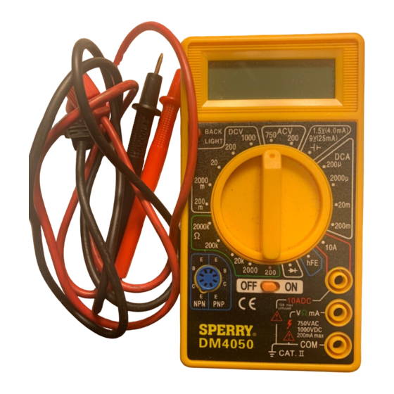
Rotary Switch
Transistor Connector
ON / OFF Button
I. DISPLAY FUNCTIONS &
SYMBOLS
Rotary Switch
Diode Test
AC - Alternating Current
DC - Direct Current
Ohm - Resistance
II. SAFETY WARNINGS
• This instruction manual contains warnings and safety rules which must be observed by
the user to ensure safe operation of the instrument and retain it in safe condition.
• Read through and understand the instructions contained in this manual before using the instrument.
• Keep the manual at hand to enable quick reference whenever necessary.
• The instrument is to be used only in its intended applications.
• Understand and follow all the safety instructions contained in the manual.
• It is essential that all safety instructions are adhered to.
• Failure to follow the safety instructions may cause injury, instrument damage
The symbol
indicated on the instrument means that the user must refer to the related parts in the
manual for safe operation of the instrument. It is essential to read the instructions wherever the symbol
appears in the manual.
Backlight
OPERATING INSTRUCTIONS
Multi-Meter
Read this owner's manual thoroughly before use and save.
Figure 1
Battery Test
mA - Millamp
A - Amp
OFF
Power Off
1
Digital
DM4050
LCD Display
Input Terminal
COM Terminal
Advertisement
Table of Contents

Related Manuals for Sperry instruments DM4050


Summary of Contents for Sperry instruments DM4050
-
Page 1: Operating Instructions
OPERATING INSTRUCTIONS Digital Multi-Meter DM4050 Read this owner’s manual thoroughly before use and save. Figure 1 LCD Display Backlight Rotary Switch Transistor Connector ON / OFF Button Input Terminal COM Terminal I. DISPLAY FUNCTIONS & SYMBOLS Rotary Switch Diode Test... - Page 2 DANGER is reserved for conditions and actions that are likely to cause serious or fatal injury. WARNING is reserved for conditions and actions that can cause serious or fatal injury. CAUTION is reserved for conditions and actions that can cause injury or instrument damage. DANGER •...
- Page 3 GENERAL SPECIFICATIONS Calibration is guaranteed for 1 year. OPERATING INSTRUCTIONS WARNING To avoid electrical shock hazard and/or damage of the instrument, do not measure voltages that WARNING might exceed 500V above earth ground. Before the use of instrument, inspect test leads, connectors and probes for cracks, breaks, or crazes WARNING in the insulation.
- Page 4 BATTERY AND FUSE REPLACEMENT 1. If “ ” appears in the display, it is indicating that the battery should be replaced. 2. Turn the meter on it’s face and remove the 2 screws. 3. Remove the back panel and locate the battery or fuse. 4.
- Page 5 Test leads, fuses, batteries and calibration are not covered under any implied warranty. “Lifetime” of products that are no longer offered by Sperry will be either repaired or replaced with an item of Sperry Instruments choice of similar value. Lifetime is defined as 5 years after Sperry discontinued manufacturing the product, but the warranty period shall be at least ten years from date of purchase.
Need help?
Do you have a question about the DM4050 and is the answer not in the manual?
Questions and answers