Table of Contents
Advertisement
CM
C
US
10
11
9
6
1.0 METER FUNCTIONS
Meter type:
Functions:
Ranges:
Display Count:
Test Lead Icons:
Input Impedance:
AC Volt Ranges:
DC Volt Ranges:
AC Amps:
DC Amps:
Resistance Ranges:
Over Range Indication:
Polarity Indication:
Electro-Magnetic:
Agency Approvals:
Operating Temperature:
32°F - 104°F (0°C_40°C)
Relative Humidity:
32°F - 86°F below <75%, 86°F - 104°F<50%
Storage Temperature:
14°F - 122°F(-10°C - 50°C)
Dimension:
179mm x 88mm x 39mm
Weight:
Around 380g (including battery)
Altitude:
Maximum 2000m
Auto-Ranging
9
10 (Auto)
3999
on display indicate proper input terminals for easy attachment of test leads
10 Meg Ohm
4V, 40V, 400V, 750V, best accuracy (1.0%+5)
400mV, 4V, 40V, 400V and 1000V, best accuracy (0.8%+1)
400µA, 4000µA, 40mA, 400mA, 4A and 10A, best accuracy (1.2%+2)
400µA, 4000µA, 40mA, 400mA, 4A and 10A, best accuracy (1.0%+2)
400ohm, 4kohm, 40kohm, 400kohm, 4Mohm, 40Mohm, best accuracy (1.0%+2)
Displayed value > 1999, displays OL (The safety and accuracy will only be guaranteed within the specification range) by the
input.
"-" is displayed for negative polarity
30 minutes
When it is under 1V/m frequency : total accuracy = assigned accuracy +5% of the range. When it is over 1V/m frequency: there
is no assigned accuracy.
ETL, CE (IEC/EN61010:, CAT III 600V, Pollution Degree 2
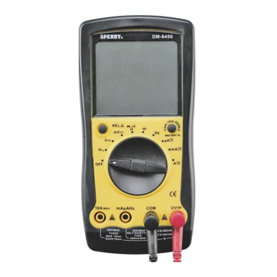
9 Function, Auto Range Digital
Multi-Meter
Read this owner's manual thoroughly before use and save.
I. DISPLAY FUNCTIONS & SYMBOLS
1. 3/12 digit LCD backlit display
2. Test Lead icons on display indicate
proper input terminals for easy
attachment of test leads
14
3. Durable drop resistant housing
4. 10 position Function dial
5. AC Volts
7. AC Amps
8. DC Amps
8
9. Resistance
10. Audible Continuity Test
11. Diode Test
15. Relative change
16. Positive input jack
17. Common input jack
18. Range select button
7
1
DM6450
Advertisement
Table of Contents

Related Manuals for Sperry instruments DM6450


Summary of Contents for Sperry instruments DM6450
-
Page 1: Operating Instructions
OPERATING INSTRUCTIONS 9 Function, Auto Range Digital Multi-Meter DM6450 Read this owner’s manual thoroughly before use and save. I. DISPLAY FUNCTIONS & SYMBOLS 1. 3/12 digit LCD backlit display 2. Test Lead icons on display indicate proper input terminals for easy attachment of test leads 3. - Page 2 2.0 READ FIRST: IMPORTANT SAFETY INFORMATION Read this operators manual thoroughly before using this multimeter. This manual is intended to provide basic information regarding this meter and to describe common test procedures which can be made with this unit. Many types of appliance, machinery and other electrical circuit measurements are not addressed in this manual and should be handled by experienced service technicians.
- Page 3 3. When the meter is not in use keep the meter turned off to keep the battery from discharging. 4. When disconnecting the test leads from the unit, always grasp the leads where the input jacks meet the tester housing. Do not pull the leads out of the jacks by the insulated wire or transport the tester using the test leads as a carrying strap.
- Page 4 4.2 DC VOLTS To avoid personal injury or damage to the Meter, do not attempt to measure voltages higher than 1000V WARNING There are five ranges for measuring DC voltage, 400mV, 4V, 40V, 400V and 1000V. For more accurate measurements use the lowest range possible without exceeding the voltage setting.
- Page 5 There are six ranges for measuring resistance 400ohm, 4Kohm, 40Kohm, 400Kohm, 4 M ohm, and 40Meg Ohms. For more accurate measurements use the lowest range possible without exceeding the setting value. when measuring resistance always make sure the power to the circuit is off. 1.
- Page 6 Notes • In a circuit, a good diode should still produce a forward voltage drop reading of 0.5V to 0.8V; however; the reverse voltage drop reading can vary depending on the resistance of other pathways between the probe tips. • Connect the test leads to the proper terminals to avoid error display. The LCD displays OL indicating open- circuit for improper connection.
- Page 7 Test leads, fuses, batteries and calibration are not covered under any implied warranty. “Lifetime” of products that are no longer offered by Sperry will be either repaired or replaced with an item of Sperry Instruments choice of similar value. Lifetime is defined as 5 years after Sperry discontinued manufacturing the product, but the warranty period shall be at least ten years from date of purchase.
Need help?
Do you have a question about the DM6450 and is the answer not in the manual?
Questions and answers