Table of Contents
Advertisement
Quick Links
Advertisement
Table of Contents

Subscribe to Our Youtube Channel
Related Manuals for Woodward SPM-D2-11


Summary of Contents for Woodward SPM-D2-11
- Page 1 37618A SPM-D2-11 Synchronizing Unit Manual From Release 7.10-0 Manual 37618A...
- Page 2 Provides other helpful information that does not fall under the warning or caution categories. Woodward reserves the right to update any portion of this publication at any time. Information provided by Woodward is believed to be correct and reliable. However, Woodward assumes no responsibility unless otherwise expressly undertaken.
-
Page 3: Copyright And Disclaimer
The manufacturer cannot be held liable for any resulting damage, the user alone bears the risk for this. As to the appropriate use of the device: The technical data and tolerances specified by Woodward have to be met. -
Page 4: Table Of Contents
Manual 37618A SPM-D2-11 - Synchronizing Unit Revision History Rev. Date Editor Change Changed product name “SPM-D-xxx” to SPM-D2-xxx” 2016-01-27 NEW 2015-12-09 Release Contents Copyright And Disclaimer ........................3 Service And Warranty ..........................3 Intended Use............................3 2. G ..................7... - Page 5 Product Service Options ......................... 78 Returning Equipment for Repair ......................78 Packing a Control ......................... 79 Return Authorization Number RAN ....................79 Replacement Parts ..........................79 How to contact Woodward ........................80 Engineering Services ..........................81 Technical Assistance ..........................82 © Woodward Page 5/83...
- Page 6 Figure 4-11: Relay outputs - control outputs II (acknowledgements) ..................16 Figure 4-12: Controller - SPM-D2-11/LSXR - three-position controller ................. 18 Figure 4-13: Controller - SPM-D2-11/LSXR - Analog controller output - Speed/frequency/real power ......... 19 Figure 4-14: Controller - SPM-D2-11/LSXR - Analog controller output - Voltage/power factor..........19 Figure 5-1: Control loop ................................
-
Page 7: Chapter 2. General Information
SPM-D2-11 - Synchronizing Unit Chapter 2. General Information The SPM-D2-11 is a synchronizing unit with integrated control functions for generator power levels and load sharing. Through the application of appropriate logic to the discrete inputs the following functions can be real- ized: ... -
Page 8: Chapter 3. Electrostatic Discharge Awareness
CAUTION To prevent damage to electronic components caused by improper handling, read and observe the pre- cautions in Woodward manual 82715, Guide for Handling and Protection of Electronic Controls, Print- ed Circuit Boards, and Modules. Page 8/83... -
Page 9: Chapter 4. Installation
Manual 37618A SPM-D2-11 - Synchronizing Unit Chapter 4. Installation WARNING A circuit breaker must be located near to the control and in a position easily accessible to the opera- tor. This must also bear a sign identifying it as an isolating switch for the control. -
Page 10: Wiring Diagram
Manual 37618A SPM-D2-11 - Synchronizing Unit Wiring Diagram ≡≡≡≡≡≡≡≡≡≡≡≡≡≡≡≡≡≡≡≡≡≡≡≡≡ SPM-D2-11/LSXR Frequency / Real Power Voltage / Power Factor Voltage Current Voltage Current Speed Speed Speed Governor Governor Governor Control: - frequency lower (f-) N.O. SPEED / REAL POWER - voltage lower (V-) -
Page 11: Reference Point
Manual 37618A SPM-D2-11 - Synchronizing Unit Reference Point ≡≡≡≡≡≡≡≡≡≡≡≡≡≡≡≡≡≡≡≡≡≡≡≡≡ Reference point Figure 4-2: Reference point Terminal Description Reference point: Neutral point of the three-phase system or neutral terminal of the voltage transformer (Measuring reference point); Sold.lug with three-conductor (delta) systems, do not connect Power Supply ≡≡≡≡≡≡≡≡≡≡≡≡≡≡≡≡≡≡≡≡≡≡≡≡≡... -
Page 12: Measuring Inputs
Connection to medium voltage via single- phase isolated transformer (e. g. Y-connection). The SPM-D2-11 may be connected to L1/L2 or L1/N. Regardless of what connection is used, the gener- ator and mains/busbar must always be connected identically. Correct measured values can be achieved for three-phase and single-phase systems if the SPM-D2-11 is configured accordingly (refer to Current Transformer section on page 44). -
Page 13: Current
If the generator load is always symmetrically, the current may also be measured in L2 or L3. This must be considered when configuring the SPM-D2-11 (refer to Current Transformer section on page 44). If there is a possibility that the load may be asymmetrical, the current must be measured in L1. -
Page 14: Discrete Inputs
Manual 37618A SPM-D2-11 - Synchronizing Unit Discrete Inputs ≡≡≡≡≡≡≡≡≡≡≡≡≡≡≡≡≡≡≡≡≡≡≡≡≡ WARNING There are two versions of this unit with different discrete inputs. The discrete inputs have different maximum voltage ratings. Look at the DATA PLATE of the unit to determine the correct voltage input ratings. -
Page 15: Analog Inputs
All controls that are load sharing must be interconnected via terminal 29 (terminals 30 must also be interconnect- ed for var sharing). If an SPM-D2-11 is switched off, the load/var sharing line must be disconnected to prevent the disabled SPM-D2-11 from influencing the other controls. -
Page 16: Relay Outputs
Manual 37618A SPM-D2-11 - Synchronizing Unit Relay Outputs ≡≡≡≡≡≡≡≡≡≡≡≡≡≡≡≡≡≡≡≡≡≡≡≡≡ max. 250 V AC Relay output external device Figure 4-10: Relay outputs - control outputs I (CB control) Root Switched Description Synchronizing pulse, Command: close CB 2.5 mm² Command: open CB for shutdown 2.5 mm²... -
Page 17: Controller Outputs
Manual 37618A SPM-D2-11 - Synchronizing Unit Controller Outputs ≡≡≡≡≡≡≡≡≡≡≡≡≡≡≡≡≡≡≡≡≡≡≡≡≡ SPM-D2-11/LSXR SPM-D2-11/LSXR controller outputs can be configured for the following signals and may require the use of an external jumper between terminals. Versions NOTE Only one controller output may be configured as three-step controller. -
Page 18: Figure 4-12: Controller - Spm-D2-11/Lsxr - Three-Position Controller
Manual 37618A SPM-D2-11 - Synchronizing Unit Setting: 'THREESTEP' (three-position controller) max. 250 Vac Relay output The relay has to be decoupled. Figure 4-12: Controller - SPM-D2-11/LSXR - three-position controller Terminal Description 2.5 mm² raise Speed / Frequency controller 2.5 mm²... -
Page 19: Figure 4-13: Controller - Spm-D2-11/Lsxr - Analog Controller Output - Speed/Frequency/Real Power
Manual 37618A SPM-D2-11 - Synchronizing Unit Setting: 'ANALOG' and 'PWM' (Analog Controller) - Frequency/real power controller Speed / power controller Speed / power controller Speed / power controller Figure 4-13: Controller - SPM-D2-11/LSXR - Analog controller output - Speed/frequency/real power... -
Page 20: Chapter 5. Description Of Functions
Manual 37618A SPM-D2-11 - Synchronizing Unit Chapter 5. Description of Functions Functional Description ≡≡≡≡≡≡≡≡≡≡≡≡≡≡≡≡≡≡≡≡≡≡≡≡≡ Table for Terminal 6 = "Enable Control" With this setting, the control can be used as an SPM-A. The status of the discrete inputs "Reply: CB is open" and "Enable CB" is displayed via the LEDs "Gen CB - ON"... -
Page 21: Table 5-2: Operating Conditions - Terminal 6 = "Off
Manual 37618A SPM-D2-11 - Synchronizing Unit Table for Terminal 6 = "Enable Power Set point Value 2" The status of the digital inputs "Reply: CB is open" and "Enable CB" is displayed via the LEDs "GCB closed" and "Release GCB" on the pressure-sensitive front membrane. Additional to the input signals the conditions listed in Table 5-3: Operating conditions - must be observed. -
Page 22: Additional Conditions
Manual 37618A SPM-D2-11 - Synchronizing Unit Additional Conditions The function of the control is also dependent, apart from the digital input signals, on the state of the available measured voltages. The particular function must also be enabled in configuration mode:... -
Page 23: Control Inputs
Manual 37618A SPM-D2-11 - Synchronizing Unit Control Inputs ≡≡≡≡≡≡≡≡≡≡≡≡≡≡≡≡≡≡≡≡≡≡≡≡≡ Terminal 6 = "Release control" Release CB Terminal 3 A signal into this discrete input enables operation of the power circuit breaker. For tests during commissioning, ensuring that no voltage is ap- plied to this input will prevent the power circuit breaker from operating, even if the control functions are enabled. -
Page 24: Isolation Of The Power Supply From The Discrete Inputs
Manual 37618A SPM-D2-11 - Synchronizing Unit Isolation of the Power Supply from the Discrete Inputs ≡≡≡≡≡≡≡≡≡≡≡≡≡≡≡≡≡≡≡≡≡≡≡≡≡ NOTE Please observe the notes about the maximum voltage ratings in the section Discrete Inputs on page By means of appropriate external wiring, the common reference point of the discrete inputs (terminal 7) can be galvanically separated from the supply voltage (0 V, terminal 2) . -
Page 25: Operating Conditions
Manual 37618A SPM-D2-11 - Synchronizing Unit Operating Conditions ≡≡≡≡≡≡≡≡≡≡≡≡≡≡≡≡≡≡≡≡≡≡≡≡≡ No Load Control The generator voltage and generator frequency are adjusted to the configured set point values. The generator cir- cuit breaker is open. Synchronization Synchronization with slip The generator voltage will be corrected to the amplitude and frequency of the synchronization voltage. The close command for the power circuit breaker will be issued, taking into account the inherent switching delay. -
Page 26: Synch-Check
Manual 37618A SPM-D2-11 - Synchronizing Unit Synch-Check In this condition, the unit can be used as a check-synchronizer. No control is carried out. The relay "Command: CB close" remains energized, as long as the following conditions are met: The configured limit for the voltage difference is met (screen "synchronization dV... -
Page 27: Shutdown
Ramp". Load Sharing The SPM-D2-11 is designed so that when several generators are operating in parallel (isolated operation) on a common mains bus, the real power of the isolated system (in reference to the relevant rated load) is shared equally among the generators. -
Page 28: Var Sharing
Manual 37618A SPM-D2-11 - Synchronizing Unit Note – Other SPM-D2-11 units, which are not participating in load sharing, must not be connected to the load sharing signal line (terminal 29) Prerequisite – The following values and adjustments of each unit in the load sharing system must be identical ... -
Page 29: Control Outputs
Manual 37618A SPM-D2-11 - Synchronizing Unit Control Outputs ≡≡≡≡≡≡≡≡≡≡≡≡≡≡≡≡≡≡≡≡≡≡≡≡≡ Synchronization pulse: Energizing this relay will close the CB. The relay de-energizes after the close Command: Close CB S schließen pulse is output. Exception: "Synch-check" operating mode. Terminals 14/15 Readiness for operation The relay contact is closed when the control is ready for operation. -
Page 30: Analog Controller Outputs
Manual 37618A SPM-D2-11 - Synchronizing Unit Analog Controller Outputs ≡≡≡≡≡≡≡≡≡≡≡≡≡≡≡≡≡≡≡≡≡≡≡≡≡ The analog PID controller forms a closed-loop control loop together with the controlled system (usually a first- order lag element). The parameters of the PID controller (proportional-action coefficient K , derivative-action... - Page 31 Manual 37618A SPM-D2-11 - Synchronizing Unit Overshoot x : Highest transient deviation from the set point value during the transition from one steady-state condition to a new steady-state condition, following a change in value of the disturbance variable or reference in- ...
-
Page 32: Figure 5-3: Step Response - Controller Set-Up
Manual 37618A SPM-D2-11 - Synchronizing Unit Controller operated as a P-only controller = [screen setting: T (where T =0], T = 0). Increase gain K (P gain) until the control loop oscillates continuously at K Pcrit CAUTION If the control starts to oscillate uncontrollably, perform an emergency shutdown and change the screen setting accordingly. -
Page 33: Chapter 6. Display And Operating Elements
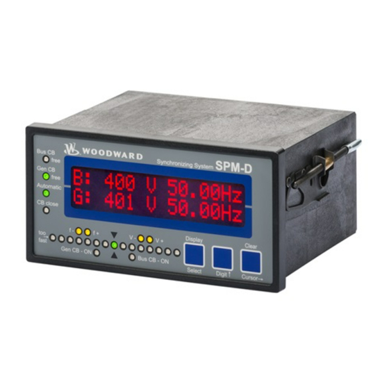
Manual 37618A SPM-D2-11 - Synchronizing Unit Chapter 6. Display and Operating Elements The foil of the front plate is made of coated plastic. All keys have been designed as touch-sensitive membrane switch elements. The display is a LC-display, consisting of 2 rows each with 16 characters, which are indirectly il- luminated red. -
Page 34: Brief Explanation Of The Leds And Push Buttons
Manual 37618A SPM-D2-11 - Synchronizing Unit Brief Explanation of the LEDs and Push Buttons ≡≡≡≡≡≡≡≡≡≡≡≡≡≡≡≡≡≡≡≡≡≡≡≡≡ LEDs No Description Function Bus CB Free Non-functional Gen CB Free Enable CB Automatic Automatic mode CB close Close command to the CB issued Synchroscope... -
Page 35: Leds
Manual 37618A SPM-D2-11 - Synchronizing Unit LEDs ≡≡≡≡≡≡≡≡≡≡≡≡≡≡≡≡≡≡≡≡≡≡≡≡≡ Bus CB Free Enable mains circuit breaker here: non-functional Color: green NOTE: This LED is non-functional, as this is a "One-power-circuit-breaker configuration". Gen CB Free Enable generator circuit breaker Color: green The LED "Gen CB Free" indicates that the power circuit breaker has been enabled for operation. - Page 36 Manual 37618A SPM-D2-11 - Synchronizing Unit Governor output decrease frequency Color: yellow Three position controller The LED "f-" indicates if the control outputs a pulse to decrease the frequen- cy. The status of the LED corresponds to the status of the relay "speed low- er".
-
Page 37: Push Buttons
Manual 37618A SPM-D2-11 - Synchronizing Unit Push Buttons ≡≡≡≡≡≡≡≡≡≡≡≡≡≡≡≡≡≡≡≡≡≡≡≡≡ Configuration may be performed by manually inputting the desired set points utilizing the pushbuttons and the LC display. In order to facilitate configuring the parameters, the push buttons have been enabled with an AUTOROLL function. -
Page 38: Lc Display
Manual 37618A SPM-D2-11 - Synchronizing Unit LC Display ≡≡≡≡≡≡≡≡≡≡≡≡≡≡≡≡≡≡≡≡≡≡≡≡≡ LC-Display LC-Display The two-line LC display outputs corresponding text messages and values depending on the mode that the SPM-D2 is operating. In the configuration mode, the monitoring parameters may be changed. When the SPM-D2 is in the automatic mode, the measured values are displayed. -
Page 39: Chapter 7. Configuration
Manual 37618A SPM-D2-11 - Synchronizing Unit Chapter 7. Configuration In order to configure the device via a PC/Notebook please proceed as follows. Install Toolkit and the USB Driver for the SPM-D2 from the CD that is provided with the product or from the webpage. -
Page 40: Configure Basic Data
Manual 37618A SPM-D2-11 - Synchronizing Unit CAUTION Please note that configuration should not be carried out while the control unit is in operation. NOTE A list of parameters may be found in the List of Parameters on page 73. The configuration mode will be enabled through the front face panel by simultaneously pressing the "Digit" and "Cursor"... -
Page 41: Password Protection
Manual 37618A SPM-D2-11 - Synchronizing Unit Password Protection The unit is equipped with a three-level code hierarchy. This permits access to different levels of selected parame- ters and configuration privileges. A distinction is made between: Code level 0 (CL0) - User: Third party This code level does not allow access to the parameters. -
Page 42: Factory Defaults
Manual 37618A SPM-D2-11 - Synchronizing Unit Factory Defaults Parameter 10417 Factory default settings Yes/No Factory default settings Yes ....Parameter 1701 (Set factory default values) will become visible. No ....Parameter 1701 (Set factory default values) will be hidden. Parameter 1701... -
Page 43: Configure Basic Settings
Manual 37618A SPM-D2-11 - Synchronizing Unit Configure Basic Settings ≡≡≡≡≡≡≡≡≡≡≡≡≡≡≡≡≡≡≡≡≡≡≡≡≡ WARNING The following values must be entered correctly to ensure proper monitoring of the generator. Failure to do so may lead to incorrect measuring of parameters resulting in damage to or destruction of the gen-... -
Page 44: Current Transformer
Manual 37618A SPM-D2-11 - Synchronizing Unit Current Transformer Generator current transformer 10 to 9.990/x A Parameter 1884 Current transf. For the indication and control of the generator current, it is necessary to enter the Generator 0000/x current transducer ratio. The ratio must be selected in a manner to ensure that at maximum power, at least 60 % of the transformer rated current is flowing. -
Page 45: Configure Controller
Manual 37618A SPM-D2-11 - Synchronizing Unit Configure Controller ≡≡≡≡≡≡≡≡≡≡≡≡≡≡≡≡≡≡≡≡≡≡≡≡≡ Entering the values in the subsequent screens will change the parameters of the controller. CAUTION Incorrect entries may lead to wrong measuring values and result in damage to the generator! Idle Control... - Page 46 Manual 37618A SPM-D2-11 - Synchronizing Unit Three-Step Controller (SPM-D2-11/LSXR: Setting 'THREESTEP') Frequency controller ON/OFF Parameter 5507 Freq. controller ON ....The generator frequency is controlled. The control is executed in var- ious manners depending on the task (no load / isolated operation /...
- Page 47 Manual 37618A SPM-D2-11 - Synchronizing Unit Analog Controller Outputs (SPM-D2-11/LSXR: Settings 'ANALOG' and 'PWM') Controller output signal see table Parameter 5201 f control output This configuration screen only appears if the frequency controller is configured as xxxxxxx ANALOG type! The range of the analog output signal is adjusted here. To choose...
- Page 48 Manual 37618A SPM-D2-11 - Synchronizing Unit Frequency controller ON/OFF Parameter 5507 Freq. controller ON ....The generator frequency is controlled. The generator frequency is controlled in various manners depending on the task (no load / isolat- LSXR Package ed operation / synchronization). The following screens of this func- with 'ANALOG' or 'PWM' setting tion are displayed.
-
Page 49: Voltage Controller
30. Voltage Controller The SPM-D2-11 is provided with a three-step controller for voltages and does not contain the following screen. Moreover, only the screens for setting the three-step controller exist. Several controller output signals can be se- lected using the following screen with the SPM-D2-11/LSXR. Depending on the selected controller type, the fol- lowing screens belonging to it appear. - Page 50 The optimum setting depends on the behavior of the system. If the gain is too low, the control action becomes slow. If the gain is configured too high, the re- sult is excessive overshoot/undershoot of the desired value. Analog Controller Outputs (SPM-D2-11/LSXR: Setting 'ANALOG') Controller output signal see table...
- Page 51 Manual 37618A SPM-D2-11 - Synchronizing Unit Voltage controller - initial state 0 to 100% Parameter 5608 V control output This parameter is the start point for the output signal when the frequency controller Init.state 000% parameter is configured as OFF. The percentage value relates to the range between...
-
Page 52: Power Factor Control
Manual 37618A SPM-D2-11 - Synchronizing Unit Voltage controller - derivative-action time 0.00 to 6.00 s Parameter 5612 Volt. controller The derivative-action time TV represents the D-component of the PID controller. Derivat.Tv=0.00s The D-component of the controller output becomes effective with large variations... - Page 53 Refer to the parameter settings for the voltage controller under Voltage Controller starting on page 49. The parameter settings performed for the voltage controller may be applied to the power factor con- troller as well. Three-Position Controller (SPM-D2-11/LSXR: Setting 'THREESTEP') Power factor controller insensitivity 0.5 to 25.0 % Parameter 5660 Pow.fact.control...
-
Page 54: Real Power Controller
Manual 37618A SPM-D2-11 - Synchronizing Unit Real Power Controller Real power controller ON/OFF Parameter 6659 Power controller ON ....During mains/parallel operation the real power is controlled to the pre-selected set point value. The following screens of this option are displayed. - Page 55 Power Set point Value NOTE The SPM-D2-11 does not take the connection to the utility into consideration. This means that if the plant generates excess power, power will be exported to the utility. If the plant does not generate enough power to meet demand, then power will be imported from the utility. This power controller does not perform process control.
- Page 56 Using this entry, frequent unnecessary actuation processes can be avoided, thus extending the life of the actuating device. Analog controller (SPM-D2-11/LSXR: Setting 'ANALOG' & 'PWM') P gain of the real power controller 1 to 240...
- Page 57 Manual 37618A SPM-D2-11 - Synchronizing Unit Power Limit The generator power is monitored for exceeding the configured threshold value. The excess is signaled with the relay "Power limit". As long as the power is below the threshold value, the relay is energized (the contact is closed).
-
Page 58: Load/Var Sharing
Manual 37618A SPM-D2-11 - Synchronizing Unit Load/Var Sharing Load sharing ON/OFF Parameter 5531 Active power ON ....Real power is distributed among the generators operating in parallel. Load-share The generator outputs are distributed depending on the set values. The following screens of this function are displayed OFF .... -
Page 59: Synchronization
Manual 37618A SPM-D2-11 - Synchronizing Unit Synchronization ≡≡≡≡≡≡≡≡≡≡≡≡≡≡≡≡≡≡≡≡≡≡≡≡≡ Configure Synchronization CAUTION Please consider that the unit does not have an internal rotating field monitoring. The unit assumes always a clockwise phase rotation direction of all voltage systems, which are meas- ured. - Page 60 Manual 37618A SPM-D2-11 - Synchronizing Unit Phase matching control ON/OFF Parameter 5729 Phase matching ON ....The synchronization is performed with phase matching control and the power circuit breaker closure is dependent upon the phase angle (refer to "Phase Matching Synchronization" on page 25). Only the pa- rameters relating to phase matching are displayed.
-
Page 61: Synchronization Time Monitoring
Manual 37618A SPM-D2-11 - Synchronizing Unit Phase matching control gain 1 to 36 Parameter 5505 Phase matching This configuration screen only appears, if the phase matching control is configured Gain Phase matching control = ON When phase matching control is enabled, this gain determines how much the output signal is changed depending on phase difference. -
Page 62: Dead Bus Start
Manual 37618A SPM-D2-11 - Synchronizing Unit Dead Bus Start ≡≡≡≡≡≡≡≡≡≡≡≡≡≡≡≡≡≡≡≡≡≡≡≡≡ If the busbar is in a voltage-free state (dead bus), a direct closing (dead bus start) of the generator circuit break- er (GCB) may be carried out. Dead bus start of power circuit breaker... -
Page 63: Configure Monitoring
Manual 37618A SPM-D2-11 - Synchronizing Unit Configure Monitoring ≡≡≡≡≡≡≡≡≡≡≡≡≡≡≡≡≡≡≡≡≡≡≡≡≡ Generator Reverse/Reduced Power Monitoring Generator real power is monitored to ensure it does not fall below a preset limit. The watchdog assigned to this relay is at terminals 37/38. The relay contact is a N.O. contact. When operating in normal operations the relay is continuously energized. -
Page 64: Generator Overload Monitoring
Manual 37618A SPM-D2-11 - Synchronizing Unit Generator Overload Monitoring Generator real power is monitored to ensure it does not exceed a preset limit. The watchdog assigned to this relay is at terminals 37/38. The relay contact is a N.O. contact. When operating in normal operations the relay is con- tinuously energized. -
Page 65: Generator Frequency Monitoring
Manual 37618A SPM-D2-11 - Synchronizing Unit Generator Frequency Monitoring Generator frequency is monitored to ensure it does not exceed or fall below the threshold value. The watchdog as- signed to this relay is at terminals 43/44. The relay contact is a N.O. contact. When operating in normal opera- tions the relay is continuously energized. -
Page 66: Generator Voltage Monitoring
Manual 37618A SPM-D2-11 - Synchronizing Unit Generator Voltage Monitoring The line voltages V of the generator are monitored to ensure they do not exceed or fall below the threshold values. The watchdog assigned to this relay is at terminals 41/42. The relay contact is a N.O. contact. When oper- ating in normal operations the relay is continuously energized. -
Page 67: Password Configuration
Manual 37618A SPM-D2-11 - Synchronizing Unit Password Configuration ≡≡≡≡≡≡≡≡≡≡≡≡≡≡≡≡≡≡≡≡≡≡≡≡≡ NOTE Once the code level is entered, access to the configuration menus will be allowed for two hours or until another password is entered into the control. If a user needs to exit a code level then code level CL0 should be entered. -
Page 68: Chapter 8. Commissioning
Manual 37618A SPM-D2-11 - Synchronizing Unit Chapter 8. Commissioning DANGER - HIGH VOLTAGE When commissioning the control, please observe all safety rules that apply to the handling of live equipment. Ensure that you know how to provide first aid in the event of an uncontrolled release of energy and that you know where the first aid kit and the nearest telephone are. - Page 69 Manual 37618A SPM-D2-11 - Synchronizing Unit Verify the status of all control and auxiliary inputs and the appropriate LEDs on the display of the control are illuminated. Verify the status of all control and auxiliary outputs as well as the settings of the controller outputs.
-
Page 70: Appendix A. Dimensions
Manual 37618A SPM-D2-11 - Synchronizing Unit Appendix A. Dimensions Configuration port Configuration port Front view Back plate mount option (please order brackets P/N 8923-1023) Bottom view 108.8 Back view with connecting terminals SPM-D11 The presence of the terminal strips depends on the Package configuration 2008-04-28 | SPM-D Dimensions spmdww-0818-ab.SKF... -
Page 71: Appendix B. Technical Data
Manual 37618A SPM-D2-11 - Synchronizing Unit Appendix B. Technical Data Measuring values, voltage ----------------------------------------------------------------------------------- Measuring voltage Rated value (V ) /........[1] 63/110 Vac rated [4] 230/400 Vac Maximum value V (UL/cUL) ....[1] max. 150 Vac Ph-Ph [4] max. 300 Vac... - Page 72 Manual 37618A SPM-D2-11 - Synchronizing Unit Analog inputs ------------------------------------------------------------------------------- freely scaleable Resolution ........................10 Bit 0/4 to 20 mA input ....................load 250 Analog outputs ------------------------------------------------------------------------------- freely scalable Resolution ........................12 Bit 0/4 to 20 mA ................. external load max. 500 ...
-
Page 73: Appendix C. List Of Parameters
Manual 37618A SPM-D2-11 - Synchronizing Unit Appendix C. List of Parameters Product number P/N _____________________________ Rev _______________________________ Version SPM-D2-11 ____________________________________________________________ Project _____________________________________________________________________ Serial number S/N _______________ Date ______________________________ Parameter Standard Adjustment range Customer settings Option 100/400V; 1/5 A setting CONFIGURE GENERAL PARAMETERS SPRACHE/LANGUAGE ... - Page 74 Manual 37618A SPM-D2-11 - Synchronizing Unit Parameter Standard Adjustment range Customer settings Option 100/400V; 1/5 A setting V contr. type T A T A THREESTEP/ANALOG ANALOG Volt. controller on off on off ON/OFF Volt.
- Page 75 Manual 37618A SPM-D2-11 - Synchronizing Unit Parameter Standard Adjustment range Customer settings Option 100/400V; 1/5 A setting CONFIGURE SYNCHRONIZATION Synchronizing functions on off on off ON/OFF Synchronization df max 0.02 to 0.49 Hz 0.18 Hz Synchronization df min 0.00 to -0.49 Hz...
-
Page 76: Appendix D. Power Factor Definition
Manual 37618A SPM-D2-11 - Synchronizing Unit Appendix D. Power Factor Definition The phasor diagram is used from the generator's view. This defines the following definitions. Power Factor is defined as a ratio of the real power to apparent power. In a purely resistive circuit, the voltage and current waveforms are instep resulting in a ratio or power factor of 1.00 (often referred to as unity). - Page 77 Manual 37618A SPM-D2-11 - Synchronizing Unit Phasor diagram: inductive capacitive © Woodward Page 77/83...
-
Page 78: Appendix E. Service Options
≡≡≡≡≡≡≡≡≡≡≡≡≡≡≡≡≡≡≡≡≡≡≡≡≡ If a control (or any part of an electronic control) is to be returned to Woodward for repair, please contact Wood- ward in advance to obtain a Return Authorization Number. When shipping the control(s), attach a tag with the fol- lowing information: ... -
Page 79: Packing A Control
Stuttgart [+49 (0) 711-789 54-0]. They will help expedite the processing of your order through our distributors or local service facility. To expedite the repair process, contact Woodward in advance to obtain a Return Authoriza- tion Number, and arrange for issue of a purchase order for the control(s) to be repaired. No work can be started until a purchase order is received. -
Page 80: How To Contact Woodward
+49 (0) 711-789 54-100 e-mail: stgt-info@woodward.com For assistance outside Germany, call one of the following international Woodward facilities to obtain the address and phone number of the facility nearest your location where you will be able to get information and service. Facility... -
Page 81: Engineering Services
Colorado, or from one of many worldwide Woodward offices or authorized distributors. Field engineers are expe- rienced on both Woodward products as well as on much of the non-Woodward equipment with which our prod- ucts interface. For field service engineering assistance, please contact us via our toll-free or local phone numbers, e-mail us, or use our website and reference field service. -
Page 82: Technical Assistance
Manual 37618A SPM-D2-11 - Synchronizing Unit Technical Assistance ≡≡≡≡≡≡≡≡≡≡≡≡≡≡≡≡≡≡≡≡≡≡≡≡≡ If you need to telephone for technical assistance, you will need to provide the following information. Please write it down here before phoning: Contact Your company _____________________________________________ Your name ________________________________________________ Phone number _____________________________________________... - Page 83 Telefon +49 (0) 711-789 54-0 Fax +49 (0) 711-789 54-101 stgt-info@woodward.com Homepage http://www.woodward.com/power Woodward has company-owned plants, subsidiaries, and branches, as well as authorized distributors and other authorized service and sales facilities throughout the world. Complete address/phone/fax/e-mail information for all locations is available on our website (www.woodward.com).
Need help?
Do you have a question about the SPM-D2-11 and is the answer not in the manual?
Questions and answers