Table of Contents
Advertisement
Quick Links
Advertisement
Table of Contents

Related Manuals for Shinybow USA SB-5548LCM


Summary of Contents for Shinybow USA SB-5548LCM
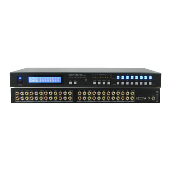
- Page 1 SB-5548LCM 8x8 Composite Video Stereo/Digital Audio Matrix Routing Switcher...
- Page 2 SAFETY INFORMATION To ensure the best results from this product, please read this manual and all other documentation before operating your equipment. Retain all documentation for future reference. Follow all instructions printed on unit chassis for proper operation. To reduce the risk of fire, do not spill water or other liquids into or on the unit, or operate the unit while standing in liquid. Make sure power outlets conform to the power requirements listed on the back of the unit.
-
Page 3: Table Of Contents
8x8 AV (Composite Video/Audio) matrix switching products on the • Do not allow anything to rest on the power cabling or allow any market today. The SB-5548LCM is a true matrix routing switcher weight to be placed upon it or any person walk on it. -
Page 4: Features & Specifications
FEATURES & SPECIFICATIONS FEATURES • Supports (8) Inputs to (8) Outputs A/V (Composite Video-Audio) Matrix Switcher • Input/Output Signals: Composite Video & Stereo Audio (AR/AL) • Higher video bandwidth 450MB each signal path • Channel selection buttons on front panel •... -
Page 5: Front Panel
FRONT PANEL FRONT PANEL 1. POWER ON SWITCH: The power switch turns the unit on and off. The LED will illuminate red to indicate that the switcher is ON and is receiving power. The switcher will remember that last state during a power cycle. When power is removed and resorted, the last configuration will be evoked. - Page 6 FRONT PANEL FRONT PANEL 8. FUNCTION KEY - ALL: Disables (mutes) video on all destinations OR Selects the same source to all destinations. Option 1 - Press ALL followed by OFF button. The display will show ”0” indicating all destinations have no video selected.
- Page 7 FRONT PANEL FRONT PANEL 12. FUNCTION KEY - MEMORY: The system will show stored presets, up to a total of 16. Presets are stored in local memory using Source keys 1 thru 8 or Destination keys 1 thru 8 as the memory preset location. - Configure desired matrices.
-
Page 8: Back Panel
BACK PANEL BACK PANEL 1. DC POWER INLET: POWER JACK: The switcher is fitted with a DC power plug input connector. Please ensure that the plug used is of an approved type DC Jack - Inner OD Ø 2.1mm (+) and is of sufficient current carrying capacity with the correct voltage Outside OD Ø... -
Page 9: Remote Control
REMOTE CONTROL Before making any connections to the SB-5548LCM Observe the following: • Ensure the main voltage supply matches the label on the supplied plug-pack (+/-10%). • Ensure that the power switch is OFF. • Ensure that all system grounds (earth) are connected to a common point. -
Page 10: Remote Protocol Commands
REMOTE PROTOCOL COMMANDS IR REMOTE CUSTOM AND DATA CODES (NEC Standard) HOW TO SETUP IR CODES : CUSTOM CODE : 2CD3 POWER ON: 2CD3 A15E LOCK: 2CD3 B54A POWER OFF: 2CD3 A25D RECALL: 2CD3 B24D ALL: 2CD3 B04F MEMORY: 2CD3 B44B OFF: 2CD3... -
Page 11: Ir Extender
IR EXTENDER IR EXTENDER 1. SB-100 IR 300M Receiver Switcher IR EXT. In Cable (3C) IR Receiver (SB-100) Distance: Max.300M IR PN#: SB-XXXX R oHS /95/E C INP UT R S -232 IR E XT. in DC 12V IR Rx RS - 232 IR EXT . -
Page 12: Rs-232 Serial Interface
RS-232 SERIAL INTERFACE RS-232 PROTOCOL COMMANDS ( RS-232 Control driver V2.0.1 ) RS-232 SERIAL CONNECT The ShinybowUSA switcher can be controlled via the RS-232 serial control port to allow for interfacing to a PC, or similar third party control system. Pin RS-232 Definition ------... -
Page 13: Typical Application
OUTPUT 1 - 8 PORT HDTV DISPLAY SIGNALS: COMPOSITE VIDEO - Composite Video, connector with RCA AUDIO - Stereo Audio (AR/AL), connector with RCA SB-5548LCM SUPPORTS (8) COMPOSITE VIDEO AND STEREO AUDIO INPUTS TO (8) COMPOSITE VIDEO AND STEREO AUDIO OUTPUTS. SUPPORTS CONTROL VIA IR & RS-232. - Page 14 LIMITED WARRANTY PLEASE READ THE FOLLOWING TERMS AND CONDITIONS CAREFULLY BEFORE USING THIS HARDWARE, COMPONENTS AND SOFTWARE PROVIDED BY, THROUGH OR UNDER SHINYBOWUSA, INC (COLLECTIVELY, THE “PRODUCT”). By using or installing the product, you unconditionally signify your agreement to these Terms and Conditions. If you do not agree to these Terms and Conditions, do not use the product and return the product to SHINYBOWUSA, Inc.
- Page 15 THIS PAGE IS INTENTIONALLY LEFT BLANK.
- Page 16 122 Rose Ln. Suite 303 | Frisco, Texas 75034 1-877-SHINY-USA 1-877-744-6987 1-972-377-2508 sales@shinybowusa.com www.shinybowusa.com...
Need help?
Do you have a question about the SB-5548LCM and is the answer not in the manual?
Questions and answers