Table of Contents
Advertisement
Quick Links
OPERATOR'S
MANUAL
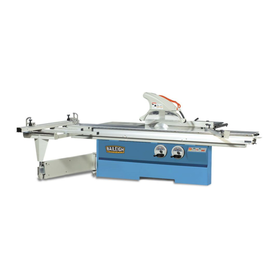
SLIDING TABLE SAW
MODEL: STS-14120
Baileigh Industrial, Inc.
P.O. Box 531
Manitowoc, WI 54221-0531
Phone: 920.684.4990
Fax: 920.684.3944
sales@baileighindustrial.com
REPRODUCTION OF THIS MANUAL IN ANY FORM WITHOUT WRITTEN APPROVAL OF BAILEIGH INDUSTRIAL, INC.
IS PROHIBITED. Baileigh Industrial, Inc. does not assume and hereby disclaims any liability for any damage or loss
caused by an omission or error in this Operator's Manual, resulting from accident, negligence, or other occurence.
Rev. 1/2013
© 2013 Baileigh Industrial, Inc.
Advertisement
Table of Contents

Subscribe to Our Youtube Channel
Related Manuals for Baileigh STS-14120


Summary of Contents for Baileigh STS-14120
- Page 1 REPRODUCTION OF THIS MANUAL IN ANY FORM WITHOUT WRITTEN APPROVAL OF BAILEIGH INDUSTRIAL, INC. IS PROHIBITED. Baileigh Industrial, Inc. does not assume and hereby disclaims any liability for any damage or loss caused by an omission or error in this Operator’s Manual, resulting from accident, negligence, or other occurence.
-
Page 2: Table Of Contents
Table of Contents THANK YOU & WARRANTY ..................1 INTRODUCTION ......................3 GENERAL NOTES......................3 SAFETY INSTRUCTIONS ....................4 SAFETY PRECAUTIONS ....................6 Dear Valued Customer: ....................6 MACHINE NOISE ......................10 SPECIFICATIONS ......................11 TECHNICAL SUPPORT ....................12 RIVING KNIFE SPECIFICATION ................13 TRANSPORTING AND LIFTING .................. - Page 3 OPERATIONAL SAFETY CHECK ................45 Emergency Stop Switch Check ................. 45 Safety Connection Switch Check ................45 CONTROL PANEL OPERATION ................46 CORRECTING CURRENT DIMENSION ..............47 SETTING PARAMETER ....................48 MAINTENANCE ......................49 Lubrication ......................... 50 Sliding Table Maintainance ..................50 Angle Slide Rail Maintenance ..................
-
Page 4: Thank You & Warranty
THANK YOU & WARRANTY Thank you for your purchase of a machine from Baileigh Industrial. We hope that you find it productive and useful to you for a long time to come. Inspection & Acceptance. Buyer shall inspect all Goods within ten (10) days after receipt thereof. Buyer’s payment shall constitute final acceptance of the Goods and shall act as a waiver of the Buyer’s rights to inspect or... - Page 5 Baileigh Industrial makes every effort to ensure that our posted specifications, images, pricing and product availability are as correct and timely as possible. We apologize for any discrepancies that may occur. Baileigh Industrial reserves the right to make any and all changes deemed necessary in the course of business including but not limited to pricing, product specifications, quantities, and product availability.
-
Page 6: Introduction
After receiving your equipment remove the protective container. Do a complete visual inspection, and if damage is noted, photograph it for insurance claims and contact your carrier at once, requesting inspection. Also contact Baileigh Industrial and inform them of the unexpected occurrence. Temporarily suspend installation. -
Page 7: Safety Instructions
IMPORTANT PLEASE READ THIS OPERATORS MANUAL CAREFULLY It contains important safety information, instructions, and necessary operating procedures. The continual observance of these procedures will help increase your production and extend the life of the equipment. SAFETY INSTRUCTIONS LEARN TO RECOGNIZE SAFETY INFORMATION This is the safety alert symbol. - Page 8 SAVE THESE INSTRUCTIONS. Refer to them often and use them to instruct others. PROTECT EYES Wear safety glasses or suitable eye protection when working on or around machinery. PROTECT AGAINST NOISE Prolonged exposure to loud noise can cause impairment or loss of hearing.
-
Page 9: Safety Precautions
• All Baileigh woodworking machines should be used only for their intended use. • Baileigh does not recommend or endorse making any modifications or alterations to a Baileigh machine. Modifications or alterations to a machine may pose a substantial risk of injury to the operator or others and may do substantial damage to the machine. - Page 10 Please enjoy your Baileigh machine! ..Please enjoy it SAFELY! FOR YOUR OWN SAFETY, READ INSTRUCTION MANUAL BEFORE OPERATING THE MACHINE. Learn the machine’s application and limitations as well as the specific hazards. Only trained and qualified personnel should operate this machine.
- Page 11 Do not overreach. Maintain proper footing and balance at all times. DO NOT reach over or across a running machine. Damaged Saw Blades. A damaged saw blade can cause kickback. If in doubt as to the condition of the blade, DO NOT use it. Stay alert.
- Page 12 Reduce the risk of unintentional starting. Make sure switch is in “OFF” position before plugging in power cord. Never leave machine running unattended. TURN POWER OFF. Don’t leave machine until it comes to a complete stop. Make sure machine is disconnected from power supply while motor is being mounted, connected or reconnected.
-
Page 13: Machine Noise
MACHINE NOISE DECLARED NOISE EMISSION VALUES in accordance with ISO 7960. Idling Operating Declared A-weighted Sound Power Level Lward, in dB re 1 pW. Declared A-weighted Emission Sound Pressure Level, lpAd, in dB re 20 μPa, at the operator’s position. Values determined according to specific test code ISO 3746. -
Page 14: Specifications
SPECIFICATIONS 22.4” x 39.3” (570 x 1000mm) Cast Iron Fixed Table Dimension 15” x 102.3” (380 x 2600mm) Sliding Table Dimension 12” (305mm) Main Saw Blade Ø 14” (355mm) optional Main Saw Blade Ø Maximum 1” (25.4mm) Main Saw Bore 4.1”... -
Page 15: Technical Support
Cutting Depths 12” (305mm) 14” (355mm) Saw Blade Diameter 10" (225mm) 0 ~ 2.16” (0 ~ 55mm) 0 ~ 3.15” (0 ~ 80mm) 0 ~ 4.13” (0 ~ 105mm) Cutting Depths At 90° 0 ~ 1.5” (0 ~ 38mm) 0 ~ 2.2” (0 ~ 56mm) 0 ~ 2.87”... -
Page 16: Riving Knife Specification
RIVING KNIFE SPECIFICATION WARNING: Before setting the riving knife, verify that it matches the saw blade diameter and body thickness. Always disconnect power at the mainpower switch prior to setting the riving knife to prevent unintended machine start up. A: Main Saw Diameter Range. B: Riving Knife Depth. -
Page 17: Transporting And Lifting
TRANSPORTING AND LIFTING CAUTION: Lifting and carrying operations should be carried out by skilled workers, such as a truck operator, crane operator, etc. If a crane is used to lift the machine, attach the lifting chain carefully, making sure the machine is well balanced. Choose a location that will keep the machine free from vibration and dust from other machinery. - Page 18 Use Lift Truck To Transport Machine • The lift truck must be able to lift at least 1.5 – 2 times the machines gross weight. • Make sure the machine is balanced. While transporting, avoid rough or jerky motion, and maintain at least 6 ft.
-
Page 19: Installation
INSTALLATION IMPORTANT: Consider the following when looking for a suitable location to place the machine: • Overall weight of the machine. • Weight of material being processed. • Sizes of material to be processed through the machine. • Space needed for auxiliary stands, work tables, or other machinery. •... -
Page 20: Clearance Dimensions
Clearance Dimensions 126” (3200mm) 33.5” (850mm) 59” (1500mm) 68” (1725mm) 71.75” (1820mm) 127” (3230mm) maximum 138.75” (3525mm) 136.5” (3470mm) -
Page 21: Unpacking And Checking Contents
UNPACKING AND CHECKING CONTENTS Your Baileigh machine is shipped complete. Separate all parts from the packing material and check each item carefully. Make certain all items are accounted for before discarding any packing material. WARNING: SUFFOCATION HAZARD! Immediately discard any plastic bags and packing materials to eliminate choking and suffocation hazards to children and animals. -
Page 22: Intended Use
INTENDED USE Table saw and the workpiece guide equipment supplied with it are intended to be used exclusively for the following purposes: • Laminated and unlaminated board materials (e.g. chipboard, coreboard, MDF board, ...) • Solid wood • Gypsum plasterboard, Cardboard, Veneer with a suitable clamping device. •... -
Page 23: Getting To Know Your Machine
GETTING TO KNOW YOUR MACHINE A B C Not only reduce dust produced by chips while Dust Guard cutting, but also warning the operator where the saw-blade position. Main Table Main working table. Rip Fence Reference positioning while ripping. Sliding Table Table for main feeding while cutting. -
Page 24: Assembly
ASSEMBLY WARNING: For your own safety, DO NOT connect the machine to the power source until the machine is completely assembled and you read and understand the entire instruction manual. Note Due to the size and weight of many of the saws components, the assembly of the complete saw will require the use of from 4 –... -
Page 25: Sliding Table Installation
SLIDING TABLE INSTALLATION The sliding table was installed and adjusted for parallelism at the factory. DO NOT change or damage the the adjusting bolts (A) during installation of the sliding table. Clean the rust preventative off of the contact surfaces (B) for the main cabinet and the sliding table (Total 3 contact surfaces). - Page 26 Check the parallelism of the sliding table to the main table. If the sliding table is parallel to the main table and has a maximum gap of 12mm between the tables and 3mm to the spindle face, final tighten the 3 mounting bolts verifying that the table does not move.
-
Page 27: Length Extension Table Installation
Install the table lock (E) onto the right end of the sliding table using the M6 x 20 screw, washer, and M6 nut (F). The lock can fasten the sliding table in the middle and the end positions. Before the sliding table is moved, make sure the safety lock is unlocked. -
Page 28: Width Cutting Extension Table Installation
WIDTH CUTTING EXTENSION TABLE INSTALLATION Locate the two extension table supports. Remove the 4 cabinet mounting bolts (A) from the back of the main cabinet and install the supports with the leveling bolt (B) up and the adjustment opening toward the outside. Tighten the cabinet mounting bolts (A) enough to hold the supports stable but allow a little movement for alignment of the leveling bolt locating bolts (D) to... -
Page 29: Crosscut Table Assembly
CROSSCUT TABLE ASSEMBLY Lubricate the pivot pin (A) with light grease and place the stand end of the crosscut table onto the pivot pin. Lift and hold the lock handle (B) so that it is pointing straight up. Place the slide end of the crosscut table on the on the slide rod (C) of the sliding table. -
Page 30: Crosscut Table Adjustment
Crosscut Table Adjustment If the crosscut table is not parallel to the working table, adjust the nut of the crosscut table and the expansion pipe and also adjust the nut in the cover plate. CROSSCUT FENCE ASSEMBLY Place the crosscut fence into the positioning point of the crosscut table. Press down the handle to secure the crosscut fence. -
Page 31: Crosscut Fence Adjustment
Crosscut Fence Adjustment Fig. 1 Fig. 2 Fig.3 Fig.4 Maintain 11-7/8” (300mm) distance between the fence and the sliding table. Use a 14” x 0.125” x 100T (355mm/3.2t/100T) blade at 5000 rpm speed and wood board 40” x 40” x 3/4" (1016 x 1016 x 19mm) for trial cut. -
Page 32: Rip Fence Assembly
RIP FENCE ASSEMBLY Install the screw on the round rod into the right side of the working table, put into the rip fence base, adjust three nuts on the round rod to make rip fence parallel to the saw blade. Use the gauge to measure the parallelism of the rip fence and the main saw blade. -
Page 33: Rip Fence Adjustment
Rip Fence Adjustment After the rip fence is moved, if the moving size and the target size have slight difference, the following is the operating way of the micro-knob: Pull the handle (A) upwards and move the rip fence to near the target size. Loosen knob (B). -
Page 34: Miter Fence Assemble
MITER FENCE ASSEMBLE Loosen the miter fence slide block clamp handle (A) a few turns. From the right end of the slide table, place the miter fence slide block over the round slide rod (B) on the front of the sliding table and slide it onto the table until it is over the angle scale. -
Page 35: Dust Guard And Support Assembly
DUST GUARD AND SUPPORT ASSEMBLY Before the machine is used to cut workpiece, make sure the dust collector work normally. Note: The required air speed at the end of flexible tube is 30 ~ 34m/sec. The required air volume of the machine is 1220 ~ 1390 m³/hr. (43,000~49,000 cu. ft./hr.). Note: Use antistatic and electrically conductive hoses only. -
Page 36: Adjust Safety Guard
ADJUST SAFETY GUARD Move the saw guard up or down slightly by hand. Adjust how tight the up/down movement of the saw guagr in by adjusting the bolt shown. This adjustment will loosen over time and must be adjusted at least tight enough to prevent the saw guard from moving when unintended. - Page 37 CHANGE SAFETY GUARD Disconnect and lockout power to the saw! Lower the saw blade fully under the saw table. Push up on the saw guard lock button to loosen the saw blade shield and move backward to remove. Fig. 1 Fig.2 Note: While cutting workpiece: At 90°...
-
Page 38: Riving Knife Adjustment
RIVING KNIFE ADJUSTMENT Disconnect and lockout power to the saw! Open the saw blade guard. Loosen the retaining screw (A) on the riving knife base just enough to allow the riving knife to move. Adjust the 3 set screws (B) at the sides of the retaining screws as the projected place shown in the above drawing. -
Page 39: Change Main Saw Blade
CHANGE MAIN SAW BLADE WARNING: Blades are dangerously sharp. Use extreme caution when working with or around the blade. Wear proper safety protection such as heavy gloves. WARNING: Turn the power switch “OFF” and unplug the power cord from its power source when changing the saw blade. When replacing blades, check the thickness stamped onto the riving knife. - Page 40 Raise the main saw blade to the highest position. Turn the saw blade until the fixing pin is inserted into the spindle fixing hole. Loosen the nut (clockwise), clean the flange and new saw blade and then install them onto the spindle.
-
Page 41: Change Spindle Rotating Speed
CHANGE SPINDLE ROTATING SPEED Disconnect and lockout power to the saw! TLower the main saw blade to the bottom position. Open the service door at the back of the machine, loosen the adjusting handle (A), press down on handle (B) to raise the motor. Main Blade Speed Lift the rotating speed knob upwards. -
Page 42: Main Saw Height And Tilting Adjustment
MAIN SAW HEIGHT AND TILTING ADJUSTMENT Hand wheel operation A. Hand wheel for main saw blade height adjustment. The arrow direction (Counterclockwise) is down. Clockwise is up. B. Hand wheel for main saw blade tilting adjustment. The arrow direction (Clockwise) increases the tilt angle. Counterclockwise decreases the tilting angle. -
Page 43: Change Scoring Saw Blade
CHANGE SCORING SAW BLADE WARNING: Blades are dangerously sharp. Use extreme caution when working with or around the blade. Wear proper safety protection such as heavy gloves. Turn the power switch “OFF” and unplug the power cord from its power source when changing the saw blade. -
Page 44: Electrical
ELECTRICAL WARNING: Baileigh Industrial is not responsible for any damage caused by wiring up to an alternative 3-phase power source other than direct 3-phase. If you are using an alternate power source, consult a certified electrician or contact Baileigh Industrial prior to energizing the machine. -
Page 45: Electrical Enclosure
WARNING: In all cases, make certain the receptacle in question is properly grounded. If you are not sure, have a qualified electrician check the receptacle • Improper connection of the equipment-grounding conductor can result in risk of electric shock. The conductor with insulation having an outer surface that is green with or without yellow stripes is the equipment-grounding conductor. -
Page 46: Power Supply Connection
Power Supply Connection Verify that the voltage of the machine conforms to your company's power. Use the specific tool to open the power controlling box to connect power. Connect three power wires to terminal L1(R), L2(S), L3(T) as shown in the Fig. 1 and Fig. 3. Connect the earth wire (green-yellow) to PE terminal. -
Page 47: Operation Overview
OPERATION OVERVIEW Safety Precautions Before Operations The operation of power tools involves a certain amount of hazard for the operator. Before attempting regular work we recommend you get the feel of operations using scrap lumber to check settings. Read entire instructions before you start to cut workpiece. Always pay attention to safety precautions to avoid personal injury. -
Page 48: Operational Safety Check
Feed the workpiece all the way through the blade while maintaining firm pressure on the workpiece against the table and fence, and keeping hands and fingers out of the blade path and away from the blade. Stops the saw immediately after the cut is complete. OPERATIONAL SAFETY CHECK IMPORTANT: Perform these safety checks at least twice every week to ensure proper and secure emergency and interlock switch function. -
Page 49: Control Panel Operation
CONTROL PANEL OPERATION Explanation Of Main Keys Item Name Description Urgently shut down the machine’s power. Emergency stop button Main saw start button Start main saw. Scoring saw start button Start scoring saw. Saw blade stop button Stop the main saw and scoring saw. Explanation of Angle Machine's Keys Item Function... -
Page 50: Correcting Current Dimension
CORRECTING CURRENT DIMENSION • The figure shows 21.5 on the display. If for example, the correct position is 35.1. The following steps will change and set the correct position. -
Page 51: Setting Parameter
SETTING PARAMETER • The figure shows 3000 as the current parameter. If for example, the correct parameter is 4255. The following steps will change and set the new pararmeter. Notes: The operators must pay attention not to make any change. Otherwise, the controller operation may be unusual and damaged the machine. -
Page 52: Maintenance
MAINTENANCE WARNING: Make sure the electrical disconnect is OFF before working on the machine. Maintenance should be performed on a regular basis following proper safety precautions. This table saw requires very little maintenance other than minor lubrication and cleaning. The following sections detail what will need to be done in order to assure continued operation of your saw. -
Page 53: Lubrication
Lubrication The table saw has sealed lubricated bearings in the motor housing and the arbor assembly, they will not require any additional lubrication. Use a wire brush to clean off the worm gears and trunnions and apply a white lithium grease to keep them lubricated. It is essential to clean components before lubricating them because dust and chips build up on lubricated components and make them hard to move. -
Page 54: Troubleshooting
TROUBLESHOOTING WARNING: Disconnect machine from the power source before attempting any troubleshooting. Trouble Check Cause Action Check if power AC 5V and AC 12V Input correct voltage. LED does not are normal. display If voltage is normal, that means Replace controller. controller is damaged. -
Page 55: Main Cabinet Parts Diagram
MAIN CABINET PARTS DIAGRAM 004 005 081 083 013 014 018 019 CE TYPE CE TYPE... - Page 56 073 072 072 073 021 020 061 063 044 045...
-
Page 57: Main Cabinet Parts List
Main Cabinet Parts List Item Description Specifications Item Description Specifications 001 Body 045 Stop Pillar 002 Electron Part Box 046 Handle Wheel Φ8 003 Cap Screw M6 x 16 047 Washer 004 Control Faceplate 048 Cap Screw M8 x 16 005 Button Head Screw M4 x 8 049 Cover... - Page 58 Item Description Specifications Item Description Specifications Φ6 034 Countersink Head Screw M6 x 16 078 Lock Washer 035 Washer 079 Cap Screw M6 x 16 036 Thrust Bearing 51102 080 Cap Screw M4 x 10 037 Bearing Base 081 Safety Switch EK-1-15-R 038 Key 5 x 5 x 15...
-
Page 59: Support Arm Parts Diagram
SUPPORT ARM PARTS DIAGRAM 001 002 003 025 024 007 014 012 016 016 017 011 010 002 001... -
Page 60: Support Arm Parts List
Support Arm Parts List Item Description Specification Button Head Screw M5 x 8 Fixed Board Clean Sheet 2.6m, 3.2m 1.9m Washer Setscrew M8 x 10 Cap Screw M8 x 16 Position Shaft Ball Bearing 6203 LLU Retain Ring STW-17 Ball Bearing 6003 ZZ Sliding Wheel Adjust Shaft... -
Page 61: Rotary Base Parts Diagram
ROTARY BASE PARTS DIAGRAM 007 008 CE TYPE 008 007 001 002 003 004 015 016 Electeon display 012 013 016 015 CE TYPE 024 023... -
Page 62: Rotary Base Parts List
Rotary Base Parts List Item Description Specification Item Description Specification Cap Screw M6 x 55 Setscrew M8 x 25 Φ6 Lock Washer Joint Bar Φ8 Washer Washer Rack Lock Nut Fixed Pole Fixed Rack Φ6 Rotary Base Washer Cap Screw M8 x 30 Cap Screw M6 x 16... -
Page 63: Main Saw Blade Mount Parts Diagram
MAIN SAW BLADE MOUNT PARTS DIAGRAM 015 016 017 010 018 008 009 020 021 022 024 025 026 024 037 042 043 038 039 040 041... -
Page 64: Main Saw Blade Mount Parts List
Main Saw Blade Mount Parts List Item Description Specification Item Description Specification Hex Head Bolt M12 x 40 8 x 7 x 20 Φ12 Lock Washer Spindle Fixed Block 8 x 7 x 32 Riving Knife (Simple) 12", 14" Button Head Screw M6 x 10 Riving Knife (Delux) 12", 14"... -
Page 65: Main Blade Elevation And Tilt Parts Diagram
MAIN BLADE ELEVATION AND TILT PARTS DIAGRAM 013 014 003 002 033 034 006 005 004 028 029 030 032 006 021 024 026 018 020... -
Page 66: Main Blade Elevation And Tilt Parts List
Main Blade Elevation and Tilt Parts List Item Description Specification Item Description Specification Hex Head Bolt M12 x 20 Gear Washer Setscrew M6 x 6 Join Block Driving Nut Fixed Base Setscrew M6 x 30 Countersink Head Screw M5 x 12 Φ6 Lock Washer Fixed Base... -
Page 67: Scoring Saw Mounting Block Parts Diagram
SCORING SAW MOUNTING BLOCK PARTS DIAGRAM 001 002 015 016 015 014 018 017 015 014 014 015 014 013 017 021 063 036 035 053 052 051 056 055 061 060 059 031 030 029 058 057 045 044 034 032 028 027 047 046 042... -
Page 68: Scoring Saw Mounting Block Parts Diagram
Scoring Saw Mounting Block Parts Diagram Item Description Specs. Item Description Specs. Control Knob 7051-42-B8 Cap Screw M8 x 30 Control Knob 7051-52-B8 Hex Nut M14 x P1.5 Fixed Block Cover Φ22 x 13t Emboss Screw 8010-25-M6-20 Cover Φ19.5 x 13t Button Head Screw M6 x 10 Cover... -
Page 69: Main Saw Motor Parts Diagram
MAIN SAW MOTOR PARTS DIAGRAM 033 020 034 008 009 035 036... -
Page 70: Main Saw Motor Parts List
Main Saw Motor Parts List Item Description Specs. Item Description Specs. Φ4 Φ10 Retain Ring Lock Washer Position Shaft Hex Nut Spring Pivot Axis Bush Spring Sheet Sensor PM08-02N-3m Hex Head Bolt M10 x 40 Cap Screw M6 x 12 Adjust Handle 95KA-M12-0 Φ6... -
Page 71: Scoring Saw Motor Parts Diagram
SCORING SAW MOTOR PARTS DIAGRAM 001 002 006 007 001 003 010 011 Scoring Saw Motor Parts List Item Description Specs. Item Description Specs. Hex Nut Spring Φ20 Lock Washer Pivot Axis Washer Stop Board Belt 15 x 690 x 1.8t Cap Screw M8 x 16 Φ12... -
Page 72: Main Table Parts Diagram
MAIN TABLE PARTS DIAGRAM 001 002 008 009 010 011 Main Table Parts List Item Description Specs. Item Description Specs. Cap Screw M8 x 20 Cap Screw M6 x 30 Protec Bar Scale Base Main Table Scale Base 1.3m Setscrew M16 x 120 Scale Base 1.5m... -
Page 73: Sliding Table Parts Diagram
SLIDING TABLE PARTS DIAGRAM 007 008 071 068 065 066 P-32 081 081 082 098 097... -
Page 74: Sliding Table Parts List
Sliding Table Parts List Item Description Specs. Item Description Specs. Sliding Table 1.9m Handle Counersink Head Sliding Table 2.6m M6 x 12 Screw Sliding Table 3.2m Retain Ring RTW-32 Scale Ball Bearing 6002 LLB Cap Screw M6 x 16 Slide Wheel Position Block Slide Wheel Shaft Button Head Screw... - Page 75 Item Description Specs. Item Description Specs. Cap Screw M8 x 20 Phillips Head Screw M5 x 8 Cap Screw M6 x 30 Cover Counersink Head Φ6 Washer M6 x 12 Screw Connect Block Position Block Connect Bar 1.9m Support Base 1.9m Connect Bar 2.6m...
-
Page 76: Crosscut Table Parts Diagram
CROSSCUT TABLE PARTS DIAGRAM 001 003 017 018 001 002 019 020 011 012 028 029 029 028... -
Page 77: Crosscut Table Parts List
Crosscut Table Parts List Item Description Specs. Item Description Specs. Rectangle Insert Fixed Board Short Lock Bar Short Retain Ring STW-14 Fixed Base Hex Nut Hex Nut Setscrew M6 x 16 Setscrew M8 x 35 Retain RIng STW-20 Adjust Block Fixed Shaft Clamp Element Crosscut Table... -
Page 78: Extension Table Parts Diagram
EXTENSION TABLE PARTS DIAGRAM 005 006 008 009 005 004 008 009 Extension Table Parts List Item Description Specs. Item Description Specs. Φ6 Table Extension Normal Washer Table Extension Support Rack Hex Nut Support Rack 1.3, 1.5m Hex Head Bolt Hex Nut Φ12 Hex Head Bolt... -
Page 79: Rip Fence Parts Diagram
RIP FENCE PARTS DIAGRAM 007 008 005 006... -
Page 80: Rip Fence Parts List
Rip Fence Parts List Item Description Specs. Item Description Specs. Fixed Base Rip Fence Hex Head Bolt M8 x 40 Screw Adjust Block Guide Key Slide Wheel Fixed Ring Countersink Head Φ8 Washer M5 x 12 Screw Lock Washer Slide Rail Hex Head Bolt M6 x 16 Slide base... -
Page 81: Crosscut Fence Parts Diagram
CROSSCUT FENCE PARTS DIAGRAM 001 002 003 004 006 007 004 003 027 026 025 024 016 017 019 048 018... -
Page 82: Crosscut Fence Parts List
Crosscut Fence Parts List Item Description Scpecs. Item Description Specs. Spring Wooden Screw 1/8" x 3/8"L Locking Slide Block Left Cover Plate Locking Bush Scale 2.6,3.2m (inch) Star-Shaped Knob HS50AM8 Scale 2.6,3.2m (inch) Postitioning Pipe 2.6m, 3.2m Scale 1.9m (inch) Postitioning Pipe 1.9m Scale... -
Page 83: Miter Fence Parts Diagram
MITER FENCE PARTS DIAGRAM 016 015 Miter Fence Parts List Item Description Specification Star-Shaped Knob 1083-810-M10 Setscrew Positioning Ring Gap Ring Setscrew M10 x 60 Locking Bushing Washer Square Insert Displacement Pipe Adjust Handle DA7012-A10 Setscrew M10 x 40 C-Fastening Block Lock Nut Damper Φ8... -
Page 84: Dust-Collecting Fastening Rack Parts Diagram
DUST-COLLECTING FASTENING RACK PARTS DIAGRAM Dust-Collecting Fastening Rack Parts List Item Description Specs. Item Description Specs. Fixed Stand Fasten Base Fixed Stand(400type) Adjust Block Fixed Base Setscrew Fixed Base 1.3m Cap Screw M8 x 16 Φ8 Fixed Base 1.5m Lock Washer Fixed Base(400type) Hex Nut Fixed Base(400type) -
Page 85: Safety Guard Connecting Arm Parts Diagram
SAFETY GUARD CONNECTING ARM PARTS DIAGRAM Safety Guard Connecting Arm Parts List Item Description Specs. Rotary Arm Rotary Arm 1.3m Rotary Arm 1.5m Connect Block Bush Cap Screw M8 x 16 Lock Shaft Fixed Block Knob 7083.710-M8 Φ8 Lock Washer Cap Screw M8 x 30 Φ8... -
Page 86: Delux Saw Guard Parts Diagram
DELUX SAW GUARD PARTS DIAGRAM 038 025034 024 015 039 037 035 048 040 034 007 008 009007 010 006... -
Page 87: Delux Saw Guard Parts List
Delux Saw Guard Parts List Item Description Specs. Item Description Specs. Push Stick Cap Screw M6 x 35 Left Safety Guard Cap Screw M6 x 25 Open/Lock Button Cap Screw M8 x 40 Φ22 Right Safety Guard Retain Ring Chip Guard Cover Ball Bearing 6900 Φ6... - Page 88 , WI 54220 UFEK RIVE ANITOWOC : 920. 684. 4990 F : 920. 684. 3944 HONE BAILEIGH BAILEIGH INDUSTRIAL, INC. 1455 S. C , CA 91761 AMPUS VENUE NTARIO : 920. 684. 4990 F : 920. 684. 3944 HONE BAILEIGH INDUSTRIAL LTD. U...
Need help?
Do you have a question about the STS-14120 and is the answer not in the manual?
Questions and answers