Table of Contents
Advertisement
OPERATOR'S
MANUAL
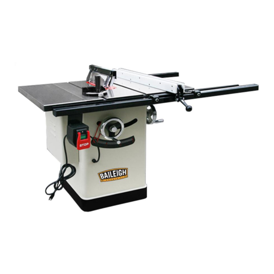
TABLE SAW
MODEL: TS-1040E 30 & 50
Baileigh Industrial, Inc.
P.O. Box 531
Manitowoc, WI 54221-0531
Phone: 920.684.4990
Fax: 920.684.3944
sales@baileighindustrial.com
REPRODUCTION OF THIS MANUAL IN ANY FORM WITHOUT WRITTEN APPROVAL OF BAILEIGH INDUSTRIAL, INC.
IS PROHIBITED. Baileigh Industrial, Inc. does not assume and hereby disclaims any liability for any damage or loss
caused by an omission or error in this Operator's Manual, resulting from accident, negligence, or other occurence.
Rev. 10/2012
© 2012 Baileigh Industrial, Inc.
Advertisement
Table of Contents

Subscribe to Our Youtube Channel
Related Manuals for Baileigh TS-1040E 30


Summary of Contents for Baileigh TS-1040E 30
-
Page 1: Table Saw
REPRODUCTION OF THIS MANUAL IN ANY FORM WITHOUT WRITTEN APPROVAL OF BAILEIGH INDUSTRIAL, INC. IS PROHIBITED. Baileigh Industrial, Inc. does not assume and hereby disclaims any liability for any damage or loss caused by an omission or error in this Operator’s Manual, resulting from accident, negligence, or other occurence. -
Page 2: Table Of Contents
Table of Contents THANK YOU & WARRANTY ..................1 INTRODUCTION ......................3 GENERAL NOTES......................3 SAFETY INSTRUCTIONS ....................4 SAFETY PRECAUTIONS ....................6 SPECIFICATIONS ......................10 INTENDED USE ......................11 Tools: ......................... 11 TECHNICAL SUPPORT ....................11 UNPACKING ......................... 12 Cleaning ........................ - Page 3 Switch Parts List ......................46 FENCE BREAKDOWN ....................47 Fence Parts List ......................47 RAIL BREAKDOWN...................... 48 Rail Parts List ......................48...
-
Page 4: Thank You & Warranty
THANK YOU & WARRANTY Thank you for your purchase of a machine from Baileigh Industrial. We hope that you find it productive and useful to you for a long time to come. Inspection & Acceptance. Buyer shall inspect all Goods within ten (10) days after receipt thereof. Buyer’s payment shall constitute final acceptance of the Goods and shall act as a waiver of the Buyer’s rights to inspect or... - Page 5 Baileigh Industrial makes every effort to ensure that our posted specifications, images, pricing and product availability are as correct and timely as possible. We apologize for any discrepancies that may occur. Baileigh Industrial reserves the right to make any and all changes deemed necessary in the course of business including but not limited to pricing, product specifications, quantities, and product availability.
-
Page 6: Introduction
After receiving your equipment remove the protective container. Do a complete visual inspection, and if damage is noted, photograph it for insurance claims and contact your carrier at once, requesting inspection. Also contact Baileigh Industrial and inform them of the unexpected occurrence. Temporarily suspend installation. -
Page 7: Safety Instructions
IMPORTANT PLEASE READ THIS OPERATORS MANUAL CAREFULLY It contains important safety information, instructions, and necessary operating procedures. The continual observance of these procedures will help increase your production and extend the life of the equipment. SAFETY INSTRUCTIONS LEARN TO RECOGNIZE SAFETY INFORMATION This is the safety alert symbol. - Page 8 SAVE THESE INSTRUCTIONS. Refer to them often and use them to instruct others. PROTECT EYES Wear safety glasses or suitable eye protection when working on or around machinery. DUST HAZARD Wear appropriate dust mask. Dust created while using machinery can cause cancer, birth defects, and long term respiratory damage.
-
Page 9: Safety Precautions
PROTECT AGAINST NOISE Prolonged exposure to loud noise can cause impairment or loss of hearing. Wear suitable hearing protective devices such as ear muffs or earplugs to protect against objectionable or uncomfortable loud noises. HIGH VOLTAGE USE CAUTION IN HIGH VOLTAGE AREAS. DO NOT assume the power to be off. - Page 10 SAFETY PRECAUTIONS (cont.) 4. Kickback. Kickback happens when the piece part is thrown back toward the operator at a high rate of speed. Before operating this saw, understand how kickback occurs, and how to prevent it. 5. Reaching Over Saw Blade. NEVER reach behind or over the blade with either hand while the saw is operating.
- Page 11 SAFETY PRECAUTIONS (cont.) 20. Stay alert. Watch what you are doing and use common sense. DO NOT operate any tool or machine when you are tired. 21. Check for damaged parts. Before using any tool or machine, carefully check any part that appears damaged.
- Page 12 SAFETY PRECAUTIONS (cont.) 36. Never leave machine running unattended. TURN POWER OFF. Don’t leave machine until it comes to a complete stop. 37. Make sure machine is disconnected from power supply while motor is being mounted, connected or reconnected. 38. Saw Appropriate Material. Only use this saw for natural wood stock and wood stock products such as particle board, plastics, laminates, and medium-density fibre board (MDF).
-
Page 13: Specifications
SPECIFICATIONS Weight 370 Lbs (168kg) 60" x 38" x 40" Dimensions L x W x H (1524 x 965 x 1016mm) Foot Print (L x W) 21-1/2" x 19-1/2" (546 x 495mm) Locking Paddle Switch with Switch Overload Protection Electrical Switch Voltage 240V Type... -
Page 14: Intended Use
34-1/4" x 3-1/8" x 2-1/2" Fence Information Fence Size (L x W x H) (870 x 80 x 63mm) Miter Gauge Slot Type T-Slot Miter Gauge Information Miter Gauge Slot Type (W x H) 3/4" x 3/8" (19 x 9.5mm) Other Information Dust Port Size 4"... -
Page 15: Unpacking
UNPACKING Remove saw from the shipping cartons. Check for damage and ensure all parts are intact. Any damage should be reported immediately to your distributor and shipping agent. Before assembling, read the manual thoroughly, familiarizing yourself with correct assembly and maintenance procedures and proper safety precautions. -
Page 16: Cleaning
Cleaning Your machine may be shipped with a rustproof waxy oil coating and grease on the exposed unpainted metal surfaces. To remove this protective coating, use a degreaser or solvent cleaner. For a more thorough cleaning, some parts will occasionally have to be removed. DO NOT USE acetone or brake cleaner as they may damage painted surfaces. -
Page 17: Geting To Know Your Machine
GETING TO KNOW YOUR MACHINE Identification Left Extension Wing; Fence Lock Handle; Miter Gauge; Blade Tilt Handwheel; Blade Guard; Blade Height Handwheel; Fence; Blade Height Lock; Back rail; Table Tilt Scale; Right Extension Wing; On/Off Switch; Front rail; Motor cover 4”... -
Page 18: Transporting And Lifting
TRANSPORTING AND LIFTING CAUTION: Lifting and carrying operations should be carried out by skilled workers, such as a truck operator, crane operator, etc. If a crane is used to lift the machine, attach the lifting chain carefully, making sure the machine is well balanced. Choose a location that will keep the machine free from vibration and dust from other machinery. -
Page 19: Installation
INSTALLATION IMPORTANT: Consider the following when looking for a suitable location to place the machine: Overall weight of the machine. Weight of material being processed. Sizes of material to be processed through the machine. Space needed for auxiliary stands, work tables, or other machinery. ... -
Page 20: Assembly
ASSEMBLY WARNING: For your own safety, DO NOT connect the machine to the power source until the machine is completely assembled and you read and understand the entire instruction manual. Remove the shipping brace Pull the switch out of the saw cabinet and remove the shipping brace. Shipping brace location Motor cover install Motor cover install... -
Page 21: Install The Rail & Fence & Extension Table
Extension wings install Remove the M10 screws from the ends of the main table. Inspect the extension wings and main table mating surfaces for burrs or foreign materials that may inhibit assembly. The mating edges of the wings and the table must be clean, smooth, and flat, use a wire brush or file if necessary to clean up the edges, this step will ensure that the wings mount properly to the main table. - Page 22 Checking fence parallelism. Slide the fence along the rail. If it drags across the table, adjust the foot at the rear of the fence to raise the fence off of the table just enough so that the gap between the fence and the table is even from front to back.
- Page 23 Install the switch Install the magnetic switch onto the bottom left hand side of the front rail using two M5-.8 x 8 hex bolts, 5mm lock washers, and 5mm flat washers. Switch install Miter gauge install Install the miter gauge Slide the miter gauge into the T-slot on the left hand side of the blade.
- Page 24 Changing the blade WARNING: Turn the power switch “OFF” and unplug the power cord from its power source when changing the saw blade. When replacing blades, check the thickness stamped onto the riving knife. You must select a blade with a kerf width larger than the thickness of the riving knife. Thinner blades may cause the workpiece to bind during cutting.
- Page 25 Install the blade guard and riving knife CAUTION: After changing a saw blade, always check that the Riving knife or Blade Guard is correctly set! Reinstall the insert, slide the knurled knob out (see Fig) and rotate it forward so it engages the upper bracket.
- Page 26 Riving Knife Thickness Saw Blade Thickness Blade Kerf (width of saw blade cut) Fig. 18 The distance of the riving knife from the gear rim must be between 3mm and 8mm. measured radially through the center of the saw spindle. As Fig.19. The highest point of the riving knife must be set beneath the topmost teeth on the blade.
- Page 27 Dust collection It is recommended that you use a dust collector (not included) when using this machine. The minimum air flow requirement for this machine are listed below. The machine comes with a 4” dust port located on the side of the machine. The dust extraction equipment is to be switched on before commencing machining.
-
Page 28: Electrical
ELECTRICAL CAUTION: HAVE ELECTRICAL UTILITIES CONNECTED TO MACHINE BY A CERTIFIED ELECTRICIAN! Check if the available power supply is the same as listed on the machine nameplate. WARNING: Make sure the grounding wire (green) is properly connected to avoid electric shock. DO NOT switch the position of the green grounding wire if any electrical plug wires are switched during hookup. -
Page 29: Extension Cord Safety
Repair or replace damaged or worn cord immediately. Extension Cord Safety Extension cord should be in good condition and meet the minimum wire gauge requirements listed below: LENGTH AMP RATING 25ft 50ft 100ft 7-10 11-12 13-16 17-20 21-30 WIRE GAUGE An undersized cord decreases line voltage, causing loss of power and overheating. -
Page 30: Adjustment
ADJUSTMENT WARNING: Make sure the electrical disconnect is OFF before working on the machine. Always follow proper safety precautions when working on or around any machinery. Before operation, the machine should be carefully adjusted for best performance. Blade Raising and Tilting Mechanism 1. -
Page 31: Aligning Table T-Slot Parallel With Blade
6. To set the fence perpendicular to the table, place a square on the table and against the side of the fence, loosen the top lock nuts (D) and adjust the setscrews (E) until the fence is perpendicular. Retighten lock nuts. 7. -
Page 32: Adjusting 45 And 90 Degree Positive Stops
Adjusting 45 and 90 Degree Positive Stops The blade tilting mechanism of your saw is equipped with a positive stop at 45 and 90 degrees. To check and adjust these positive stops, proceed as follows: 1. Raise the saw blade to its maximum height. 2. - Page 33 6. Be positive the edge of workpiece next to face of miter gauge is straight and tight against miter gauge so that the workpiece does not rock or rotate. Always use both hands when operating the miter gauge. 7. The miter gauge is used for crosscutting, compound miter cutting, rabbeting, bevel cutting and dadoing.
-
Page 34: Operation
OPERATION Safety Precautions Before Operations The operation of power tools involves a certain amount of hazard for the operator. Before attempting regular work we recommend you get the feel of operations using scrap lumber to check settings. Read entire instructions before you start to cut workpiece. Always pay attention to safety precautions to avoid personal injury. -
Page 35: Crosscutting
Crosscutting Crosscutting requires the use of the miter gauge to position and guide the workstock. Place the workstock against the miter gauge and advance both the miter gauge and workstock toward the saw blade. The miter gauge may be used in either table slot, however, most operators prefer the left groove for average work. -
Page 36: Using Dado Blade Set And Dado Insert
Using Dado Blade Set and Dado Insert WARNING: Blades are dangerously sharp. Use extreme caution when working with or around the blade. Wear proper safety protection such as heavy gloves. Dadoing is cutting a rabbet or a wide groove into the work. Most dado head sets are made up of two outside blades and four or five inside cutters, as shown in Fig. -
Page 37: Maintenance
MAINTENANCE WARNING: Make sure the electrical disconnect is OFF before working on the machine. Maintenance should be performed on a regular basis following proper safety precautions. This table saw requires very little maintenance other than minor lubrication and cleaning. The following sections detail what will need to be done in order to assure continued operation of your saw. -
Page 38: Lubrication
Lubrication The table saw has sealed lubricated bearings in the motor housing and the arbor assembly, they will not require any additional lubrication. Use a wire brush to clean off the worm gears and trunnions and apply a white lithium grease to keep them lubricated. Changing Belts 1. -
Page 39: Troubleshooting
TROUBLESHOOTING WARNING: Disconnect machine from the power source before attempting any troubleshooting PROBLEM SOLUTION SAW WILL NOT START 1. Saw not plugged in. 1. Plug in saw. 2. Fuse blown or circuit breaker tripped. 2. Replace fuse or reset circuit breaker. 3. - Page 40 BLADE DOES NOT COME UP TO SPEED 1. Extension cord too light or too long. 1. Replace with adequate size extension cord. 2. Low house current. 2. Contact your electric company. 3. Motor not wired for correct voltage. 3. Refer to motor and /or nameplate. MACHINE VIBRATES EXCESSIVELY 1.
-
Page 41: Table Saw Body Breakdown
TABLE SAW BODY BREAKDOWN... -
Page 42: Table Saw Body Parts List
Table Saw Body Parts List Item Description Qty. Item Description Qty. Extension Wing 6-1 x 12mm Phlp Head Screw 10-1.25 x 25mm Hex Head Bolt Lock Washer 6mm Lock Washer 10mm Flat Washer (W) 6mm Flat Wwasher 10mm Cabinet Plate Table Flat Washer 5mm Lock Washer 5mm... -
Page 43: Trunnion Assembly Breakdown
TRUNNION ASSEMBLY BREAKDOWN... -
Page 44: Trunnion Assembly Parts List
Trunnion Assembly Parts List Item Description Qty. Item Description Qty. Hex Head Bolt 8-1.25 x 16mm 6-1.0 x 20mm Skt Head Bolt Lock Washer 8mm Spring Fiber Hex Nut 16-2.0mm Limit Ring Flat Washer (W) 8mm Locking Pin Flat Washer 16mm Locking Plate Motor Stop Collar... - Page 45 Item Description Qty. Item Description Qty. Lock Washer 10mm Elevation Shaft Flat Washer 10mm Spacer Shim Front Trunnion Rear Trunnion Bushing Shim Washer Spring Spring Plate Wave Washer 5-0.8mm Fiber Hex Nut 90° Lock Collar Mounting Plate 45° Lock Collar Bracket 5-.8 x 16mm Socket Head Bolt Knurled Knob...
-
Page 46: Blade Guard Breakdown
BLADE GUARD BREAKDOWN... -
Page 47: Blade Guard Parts List
Blade Guard Parts List Item Description Qty. Item Description Qty. Roll Pin 4 x 20 Hex Bolt M4-.7 x 8 Torsion Spring Guard Support Lock Nut M6-1 Phlp Hd Scr M6-1 x 30 Supporting Arm Spacer Phlp Hd Scr M6-1 x 25 Spacer Flat Washer 6mm Phlp Hd Scr M5-.8 x 20... -
Page 48: Miter Gauge Breakdown
MITER GAUGE BREAKDOWN Miter Gauge Parts List Item Description Qty. Item Description Qty. Plug Flat Washer 4mm Knob Pointer Spacer Block Miter Gauge Stop Pin Hex Nut 5-0.8mm Pan Head Screw 5-0.8 x 20mm Flat Head Screw 4-0.7 x 10mm Pan Head Screw 4-0.7 x 10mm Washer Flat Head Screw 6-1.0 x 8mm... -
Page 49: Switch Breakdown
SWITCH BREAKDOWN Switch Parts List Item Description Qty. Item Description Qty. Pan Head Tapping Screw Flat Washer 5mm ST3.5 x 18 202 Switch (Hy56) Connection Port 203 Switch Box Serrated Washer 5mm 204 Circuit Breaker,10A Switch Plate Pan Head Tapping Screw 205 Nut ST3.9 x 10 206 Pan Head Screw 5-0.8 x 8mm... -
Page 50: Fence Breakdown
FENCE BREAKDOWN Fence Parts List Item Description Qty. Item Description Qty. 501 Glide Pad Fence Lock Knob 502 Special Locking Nut M12-1.75 Lock Nut M10-1.25 503 Set Screw M12-1.75 x 15 Phlp Hd Scr M5-.8 x 25 504 Set Screw Lock Washer 5mm 505 Hex Bolt M6-1 x 40 Fence Scale Window... -
Page 51: Rail Breakdown
RAIL BREAKDOWN Rail Parts List Item Description Qty. Item Description Qty. Rear Rail Lock Washer 6mm Flat Washer 10mm Socket Head Bolt M6-1 x 16 Lock Washer 10mm Fence Insert 40 x 50 Socket Head Bol M10-1.5 x 25 Scale Socket Head Bol M8-1.25 x 35 Guide Tube Flat Washer 8mm... - Page 52 , WI 54220 UFEK RIVE ANITOWOC : 920. 684. 4990 F : 920. 684. 3944 HONE BAILEIGHINDUSTRIAL BAILEIGH INDUSTRIAL, INC. 1455 S. C , CA 91761 AMPUS VENUE NTARIO : 920. 684. 4990 F : 920. 684. 3944 HONE BAILEIGH INDUSTRIAL LTD. U...
Need help?
Do you have a question about the TS-1040E 30 and is the answer not in the manual?
Questions and answers