Table of Contents
Advertisement
Quick Links
OPERATOR'S
MANUAL
36" & 52" TABLE SAW
MODEL: TS-1248P
Baileigh Industrial, Inc.
P.O. Box 531
Manitowoc, WI 54221-0531
Phone: 920.684.4990
Fax: 920.684.3944
sales@baileigh.com
REPRODUCTION OF THIS MANUAL IN ANY FORM WITHOUT WRITTEN APPROVAL OF BAILEIGH INDUSTRIAL, INC.
IS PROHIBITED. Baileigh Industrial, Inc. does not assume and hereby disclaims any liability for any damage or loss
caused by an omission or error in this Operator's Manual, resulting from accident, negligence, or other occurrence.
Rev. 10/2016
© 2016 Baileigh Industrial, Inc.
Advertisement
Table of Contents

Related Manuals for Baileigh TS-1248P


Summary of Contents for Baileigh TS-1248P
- Page 1 REPRODUCTION OF THIS MANUAL IN ANY FORM WITHOUT WRITTEN APPROVAL OF BAILEIGH INDUSTRIAL, INC. IS PROHIBITED. Baileigh Industrial, Inc. does not assume and hereby disclaims any liability for any damage or loss caused by an omission or error in this Operator’s Manual, resulting from accident, negligence, or other occurrence.
-
Page 2: Table Of Contents
Table of Contents THANK YOU & WARRANTY ..................1 INTRODUCTION ......................3 GENERAL NOTES ......................3 SAFETY INSTRUCTIONS ....................4 SAFETY PRECAUTIONS ....................6 Dear Valued Customer: ....................6 SPECIFICATIONS ......................10 TECHNICAL SUPPORT ....................12 UNPACKING AND CHECKING CONTENTS ..............13 Cleaning ........................ - Page 3 Cutting Dadoes with a Standard Blade ..............48 Rabbet Cutting ......................49 Cutting Rabbets with a Dado Blade ................49 Cutting Rabbets with a Standard Blade ..............50 CUTTING TOOLS (OPTIONAL)..................51 Outfeed & Support Tables ..................51 ADJUSTMENT ......................52 Blade Height Adjustment ...................
- Page 4 52” Saw Body Parts List A & B .................. 94...
-
Page 5: Thank You & Warranty
THANK YOU & WARRANTY Thank you for your purchase of a machine from Baileigh Industrial. We hope that you find it productive and useful to you for a long time to come. Inspection & Acceptance. Buyer shall inspect all Goods within ten (10) days after receipt thereof. Buyer’s payment shall constitute final acceptance of the Goods and shall act as a waiver of the Buyer’s rights to inspect or... - Page 6 Baileigh Industrial makes every effort to ensure that our posted specifications, images, pricing and product availability are as correct and timely as possible. We apologize for any discrepancies that may occur. Baileigh Industrial reserves the right to make any and all changes deemed necessary in the course of business including but not limited to pricing, product specifications, quantities, and product availability.
-
Page 7: Introduction
After receiving your equipment remove the protective container. Do a complete visual inspection, and if damage is noted, photograph it for insurance claims and contact your carrier at once, requesting inspection. Also contact Baileigh Industrial and inform them of the unexpected occurrence. Temporarily suspend installation. -
Page 8: Safety Instructions
IMPORTANT PLEASE READ THIS OPERATORS MANUAL CAREFULLY It contains important safety information, instructions, and necessary operating procedures. The continual observance of these procedures will help increase your production and extend the life of the equipment. SAFETY INSTRUCTIONS LEARN TO RECOGNIZE SAFETY INFORMATION This is the safety alert symbol. - Page 9 SAVE THESE INSTRUCTIONS. Refer to them often and use them to instruct others. PROTECT EYES Wear safety glasses or suitable eye protection when working on or around machinery. PROTECT AGAINST NOISE Prolonged exposure to loud noise can cause impairment or loss of hearing.
-
Page 10: Safety Precautions
All Baileigh woodworking machines should be used only for their intended use. Baileigh does not recommend or endorse making any modifications or alterations to a Baileigh machine. Modifications or alterations to a machine may pose a substantial risk of injury to the operator or others and may do substantial damage to the machine. - Page 11 1. FOR YOUR OWN SAFETY, READ INSTRUCTION MANUAL BEFORE OPERATING THE MACHINE. Learn the machine’s application and limitations as well as the specific hazards. 2. Only trained and qualified personnel should operate this machine. 3. Make sure guards are in place and in proper working order before operating machinery.
- Page 12 19. Damaged Saw Blades. A damaged saw blade can cause kickback. If in doubt as to the condition of the blade, DO NOT use it. 20. Stay alert. Watch what you are doing and use common sense. DO NOT operate any tool or machine when you are tired.
- Page 13 36. Never leave machine running unattended. TURN POWER OFF. Don’t leave machine until it comes to a complete stop. 37. Make sure machine is disconnected from power supply while motor is being mounted, connected or reconnected. 38. Saw Appropriate Material. Only use this saw for natural wood stock and wood stock products such as particle board, plastics, laminates, and medium-density fiber board (MDF).
-
Page 14: Specifications
SPECIFICATIONS Blade 12” Maximum Blade Diameter 0.09” (2.3mm) Riving Knife/Spreader Thickness 0.074” - 0.082” (1.9 - 2.1mm) Required Blade Body Thickness 0.114” - 0.122” (2.9 - 3.1mm) Required Blade Kerf Thickness 3/4” (19mm) Maximum Width of Dado Blade Tilt Left 0-45 Deg. 1”... - Page 15 Motor Type 5Hp (3.72Kw) TEFC Induction Supply Voltage 220V, 1Ph, 60Hz Motor Current Speed 3600 RPM 1 @ 4” (102mm) Dust Port Product Dimensions: 36” Net Weight 640 lbs. (290kg) 52” 715 lbs. (324kg) 36” 79” x 49” x 42.5” (2006 x 1244 x 1080mm) Overall Dimensions (W x D x H) 52”...
-
Page 16: Technical Support
(other than die sets and blades). For specific application needs or future machine purchases contact the Sales Department at: sales@baileigh.com, Phone: 920.684.4990, or Fax: 920.684.3944. Note: The photos and illustrations used in this manual are representative only and may not depict the actual color, labeling or accessories and may be intended to illustrate technique only. -
Page 17: Unpacking And Checking Contents
UNPACKING AND CHECKING CONTENTS Your Baileigh machine is shipped complete. Separate all parts from the packing material and check each item carefully. Make certain all items are accounted for before discarding any packing material. WARNING: SUFFOCATION HAZARD! Immediately discard any plastic bags and packing materials to eliminate choking and suffocation hazards to children and animals. - Page 18 Item Contents Qty. Table Saw Cast Iron Extension Wing Blade 12” Spreader/Guard Push Stick Wrenches Handwheel Handles Fence Resting Brackets Miter Gauge Miter Gauge Handle Fence Tube (75" long) Front Rail (75" long) Rear Rail (62-1⁄2" long) Fence Fence Handle...
-
Page 19: Transporting And Lifting
TRANSPORTING AND LIFTING IMPORTANT: Lifting and carrying operations should be carried out by skilled workers, such as a truck operator, crane operator, etc. If a crane is used to lift the machine, attach the lifting chain carefully, making sure the machine is well balanced. Follow these guidelines when lifting with truck or trolley: ... - Page 20 Remove scrap and waste materials regularly, and make sure the work area is free from obstructing objects. It is important to maintain free area around the machine, which is required for the working place. If any long material is machined, it is necessary to have a sufficient room in front of the machine as well behind it in the places of material input and output.
-
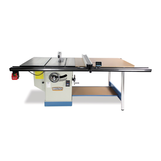
Page 21: Getting To Know Your Machine
GETTING TO KNOW YOUR MACHINE 52” Shown with Extension. Extension Table not included with 36” model. Item Description Item Description Main Table Front Fence Rail Tube Support Stand (52” only) Miter Gauge Storage Table (52” only) Fence Scale Indicator Blade Guard and Spreader Blade Tilt Handwheel w/Lock Blade Guard Table Insert Tilt Angle Digital Read Out... -
Page 22: Assembly And Set Up
ASSEMBLY AND SET UP WARNING: For your own safety, DO NOT connect the machine to the power source until the machine is completely assembled and you read and understand the entire instruction manual. 1. Fasten the front rail onto the main table with (4) M8-1.25 x 25 flat head screws (A). -
Page 23: Extension Wing 36" Models
Extension Wing 36” Models 1. Inspect the extension wing and main table mating surfaces for burrs or foreign materials. The mating edges of the wing and the table must be clean, smooth, and flat. Use a wire brush or file if necessary to clean up the edges. This step will ensure that the wing mounts properly to the main table. -
Page 24: Extension Table 52" Models
Extension Table 52” Models 1. With help of an assistant, install the extension table hand tight until all hardware is installed and the table is both flush and flat with the main table. 2. Thread (2) M10-1.5 x 25 hex bolts with 10mm flat washers onto the right side of the main table (A). - Page 25 8. Fasten the support legs (E) to the main extension table with (8) M6-1 x 12 Phillips head screws and 6mm flat washers (F). 9. Adjust both feet until they touch the ground with firm pressure without lifting the extension table, and tighten the hex nuts against the legs to secure the feet.
-
Page 26: On/Off Switch, Fence, Gauge, And Mounts
On/Off Switch, Fence, Gauge, and Mounts 1. Install the fence tube (A) onto the fence rail using (7) M8-1.25 x 25 bolts. Verify that the gap between the rail tube and the rail mount is even along the entire length and tighten the bolts. 2. -
Page 27: Dust Collection
11. Follow the instructions in Dust collection, power connection and Test Run, and then proceed to Final Setup to complete the remaining assembly steps. The remaining tasks required for assembling the saw include: Installing the table insert and cutting a slot for the blade, checking fence parallelism, installing the blade guard, and calibrating the blade angle digital readout. -
Page 28: Electrical
ELECTRICAL CAUTION: HAVE ELECTRICAL UTILITIES CONNECTED TO MACHINE BY A CERTIFIED ELECTRICIAN! Check if the available power supply is the same as listed on the machine nameplate. WARNING: Make sure the grounding wire (green) is properly connected to avoid electric shock. DO NOT switch the position of the green grounding wire if any electrical plug wires are switched during hookup. -
Page 29: Power Supply Connection
Improper connection of the equipment-grounding conductor can result in risk of electric shock. The conductor with insulation having an outer surface that is green with or without yellow stripes is the equipment-grounding conductor. If repair or replacement of the electric cord or plug is necessary, do not connect the equipment-grounding conductor to a live terminal. -
Page 30: Initial Operation
INITIAL OPERATION Once the assembly is complete, run your machine to make sure it runs properly and is ready for regular operation. Operators familiar with this saw should follow this procedure on a regular basis; approximately every 3 month. Operators new to the saw should be trained by a qualified operator familiar with table saw operation and follow this procedure daily for approximately 1 –... -
Page 31: Operation Overview
OPERATION OVERVIEW Safety Precautions Before Operations The operation of power tools involves a certain amount of hazard for the operator. Before attempting regular work, we recommend you get the feel of operations using scrap lumber to check settings. Read entire instructions before you start to cut workpiece. Always pay attention to safety precautions to avoid personal injury. -
Page 32: Non-Through & Through Cuts
9. Feed the workpiece all the way through the blade while maintaining firm pressure on the workpiece against the table and fence, and keeping hands and fingers out of the blade path and away from the blade. 10. Stops the saw immediately after the cut is complete. Non-Through &... -
Page 33: Blade Requirements
Large/Loose Knots: Loose knots can become dislodged during the cutting operation. Large knots can cause kickback and machine damage. Choose workpieces that do not have large/loose knots or plan ahead to avoid cutting through them. Wet or "Green" Stock: Cutting wood with a moisture content over 20% causes unnecessary wear on the blades, increases the risk of kickback, and yields poor results. - Page 34 Crosscut Blade Features Best for cutting across the grain 60-80 teeth Alternate top bevel tooth profile Small hook angle and a shallow gullet Combination Blade Features Designed to cut both with and across grain 40-50 teeth ...
-
Page 35: Dado Blades
Dado Blades Stacked Dado Blade Multiple blades are stacked together to control the cutting width. Stacked dado blades are more expensive than wobble blades, but typically produce higher quality results. Wobble Dado Blade A single blade mounted at a slight angle on an arbor hub. The blade angle is adjustable on the hub, and the width of the dado cut is controlled by the angle setting of the blade. -
Page 36: Blade Installation
BLADE INSTALLATION WARNING: Blades are dangerously sharp. Use extreme caution when working with or around the blade. Wear proper safety protection such as heavy gloves. WARNING: Turn the power switch “OFF” and unplug the power cord from its power source when changing the saw blade. When replacing blades, check the thickness stamped onto the riving knife. -
Page 37: Blade Guard Assembly
BLADE GUARD ASSEMBLY The blade guard refers to the assembly that consists of the clear shield, the spreader, and the anti-kickback pawls on each side of the spreader. Each of these components has important safety functions. Guard The clear shield reduces injury risk by providing a barrier around the blade that prevents accidental contact and contains flying wood chips. -
Page 38: Installing Blade Guard & Spreader
Installing Blade Guard & Spreader 1. Disconnect and lockout power to the saw! 2. Remove the table insert. 3. Insert the spreader into the bracket slot and tighten the lock knob to secure the spreader. 4. Tug upward on the top of the spreader to verify it is locked. -
Page 39: Anti-Kickback Pawls
Anti-Kickback Pawls The anti-kickback pawls allow the workpiece to travel in only one direction. If the workpiece moves backwards, such as during a kickback, the pawls will dig into the workpiece to slow or stop it. To work properly, the pawls must freely return to their resting position with contact to the table surface after pivoting. - Page 40 Installing Pawls 1. Loosen the knob on top of the spreader, and then remove the blade guard. 2. Slide the pin in the pawl block into the second groove from the front of the spreader. 3. Press the button on the pawl block, and then pivot the pawls down until they lock into place.
-
Page 41: Riving Knife
RIVING KNIFE The riving knife is very similar to the spreader on the blade guard assembly. It is a metal plate that prevents the newly cut workpiece from pinching the backside of the blade and causing kickback. It also acts as a barrier behind the blade to reduce the risk of hands being pulled into the blade if kickback occurs. - Page 42 How to Install the Riving Knife Install the riving knife in the same manner as the blade guard and spreader. See the blade Guard and Spreader installation. When to Use the Riving Knife Use the riving knife for all non-through cuts made with a standard table saw blade (i.e., dadoes or rabbet cuts, and when using a tenoning jig).
-
Page 43: Cutting A Zero Clearance Insert
CUTTING A ZERO CLEARANCE INSERT A zero-clearance insert is provided with the table saw to reduce workpiece tear out and increase operator safety. The insert can be customized to fit a specific blade height or blade angle for the applicable cutting operation. 1. -
Page 44: Operation
OPERATION Safety Precautions Before Operations The operation of power tools involves a certain amount of hazard for the operator. Before attempting regular work, we recommend you get the feel of operations using scrap lumber to check settings. Read entire instructions before you start to cut workpiece. Always pay attention to safety precautions to avoid personal injury. -
Page 45: Operation
Operation Plain sawing includes ripping and crosscutting, plus a few other standard operations of a fundamental nature. The following methods feature safety. As with all power tools there is a certain amount of hazard involved with the operation and use of the tool. Using the tool with the respect and caution demanded as far as safety precautions are concerned will considerably lessen the possibility of personal injury. - Page 46 • If the work to be ripped is narrow, it is safer to use a push stick, rather than the hands, to feed it into the blade. Push sticks with non-slip grippers can be purchased, but shop-made push sticks work just as well. When ripping extremely narrow stock that may not clear the width of the blade guard, or very thin material such as paneling, which may slip between the underside of the...
-
Page 47: Miter Ripping
10. Advance the workstock using push sticks as needed, through the saw blade holding it down and against the fence until the workpiece is completely beyond the saw blade. Never, stand in the line of the saw cut when ripping. 11. - Page 48 WARNING: Keep the blade guard installed and in the down position. Failure to do this could result in serious personal injury or death. Never reach in towards the blade while the blade is still spinning! Whenever a cut is completed, turn off the saw and wait for the blade to come to a complete stop before reaching in to remove the workpiece or the waste material.
-
Page 49: Miter Cross Cutting
9. Lower the blade guard. 10. Start the saw and make the cut. When the work is cut through, move one or both cut pieces. If long enough to handle without danger immediately off to the side, away from the turning blade. 11. -
Page 50: Dado Cutting
Dado Cutting WARNING: Blades are dangerously sharp. Use extreme caution when working with or around the blade. Wear proper safety protection such as heavy gloves. Dadoing is cutting a rabbet or a wide groove into the workpiece that does not cut all the way through the material. -
Page 51: Cutting Dadoes With A Dado Blade
WARNING: NEVER use the dado head in a bevel position unless you make your own dado insert! ALWAYS install blade guard after operation is complete! DO NOT make through cuts with a dado blade. Dado blades are only intended for non- through cuts. -
Page 52: Cutting Dadoes With A Standard Blade
1. Reconnect the saw to the power source. 2. Turn the saw ON. The blade should run smoothly, with no vibrations. 3. When the blade has reached full speed, perform a test cut with a scrap piece of wood. 4. If the cut is satisfactory, repeat the cut with the actual workpiece. Cutting Dadoes with a Standard Blade A ripping blade is typically the best blade to use when cutting dadoes with a standard blade because it removes sawdust very efficiently. -
Page 53: Rabbet Cutting
Rabbet Cutting A rabbet is an L-shaped groove cut in the edge of the workpiece. Rabbets can be cut with either a dado blade or a standard saw blade. Rabbet cutting on the edge of the workpiece with a dado blade requires a sacrificial fence. Make the sacrificial fence the same length as the fence and 3/4"... -
Page 54: Cutting Rabbets With A Standard Blade
Cutting Rabbets with a Standard Blade A ripping blade is typically the best blade to use for cutting rabbets when using a standard blade because it removes sawdust very efficiently. Also, a sacrificial fence is not required when cutting rabbets with a standard blade. To cut rabbets with the standard blade: 1. -
Page 55: Cutting Tools (Optional)
CUTTING TOOLS (OPTIONAL) Cutting tools such as push sticks (one included with the saw), push blocks, featherboard, crosscut sleds, etc. are extremely useful in providing additional safety as well as added accuracy to your cut. While these types of tools may be purchased, they are often the first projects to be completed when setting up shop. -
Page 56: Adjustment
ADJUSTMENT WARNING: Make sure the electrical disconnect is OFF before working on the machine. Always follow proper safety precautions when working on or around any machinery. Before operation, the machine should be carefully adjusted for best performance. Blade Height Adjustment CAUTION: To limit your exposure to the blade and maximize the effectiveness of the anti-kickback pawls (when using the riving style splitter &... -
Page 57: Adjusting The 90° Bevel Stop
Adjusting the 90° Bevel Stop Note: The tilt scale reads "0" when the blade is 90° to the table. 90° Check and Adjustment 1. Disconnect and lockout power to the saw! 2. Raise the blade to its highest position and tilt it toward 0° until it stops and cannot be tilted any more. -
Page 58: Adjusting The 45° Bevel Stop
Adjusting the 45° Bevel Stop 1. Disconnect and lockout power to the saw! 2. Raise the blade as high as it will go, then tilt it towards 45° until it stops and cannot be tilted any more. 3. Place a 45° square against the table and blade so it contacts the blade evenly from bottom to top Verify that a blade tooth does not obstruct the placement of the square. -
Page 59: Blade Tilt Angle Digital Readout Calibration
5. Loosen the cap screws and the jam nut (A). 6. Tightens the adjustment hex bolt slightly and recheck the backlash. 7. Proper backlash will be when no backlash is felt without being so tight as to bind the gears. 8. -
Page 60: Miter Slot To Blade Parallelism
Miter Slot to Blade Parallelism The table saw will provide best results if the miter slot and the rip fence are adjusted parallel to the blade. If either of these is not exactly parallel, your cuts and your finished work will be lower in quality, but more importantly, the risk of kickback will be increased. - Page 61 45° Check and Adjustment 1. Tilt the blade to 45° and repeat Steps 3 – 6. If the blade is still parallel with the miter slot, continue onto the Blade Alignment procedure. If the blade was parallel with the miter slot at 90° but not at 45°, one end of the table will need to be shimmed higher with metal shim stock.
-
Page 62: Spreader Or Riving Knife Alignment
Spreader or Riving Knife Alignment Checking Alignment The blade guard spreader and riving knife must be aligned with the blade when installed. If the spreader/riving knife is not aligned with the blade, then the workpiece will be forced sideways during the cut, which will increase the risk of kickback. 1. -
Page 63: Fence Adjustments
4. Loosen the upper and lower cap screws (B), then adjust the 4 set screws in or out until the alignment is perfectly parallel. 5. Reinstall the table insert. Adjusting Bent Spreader/Riving Knife 1. Disconnect and lockout power to the saw! 2. -
Page 64: Offsetting Fence
3. Adjust the set screws (B) on top of the fence bracket. 4. Loosen each set screw until there is no pressure between the set screw and the fence rail. 5. Turn the sets screws in until the fence face is 90° to the table while attempting to not raise the fence to create a gap greater than 1/16”. -
Page 65: Clamping Pressure And Parallelism
Clamping Pressure and Parallelism The fence clamping mechanism adjusts the clamping pressure to hold your fence securely and to position the fence parallel with the blade. Checking Fence Parallelism: 1. Disconnect and lockout power to the saw! 2. Verify that the fence gap is correct. 3. -
Page 66: Fence Scale Calibration
Fence Scale Calibration The fence scale indicator windows can be calibrated with the fence scale by loosening the two mounting screws (A) and sliding it in the desired direction. 1. Position and lock the fence at 13", as indicated by the scale, then cut your scrap piece of wood. -
Page 67: Fence Dro Installation And Calibration
FENCE DRO INSTALLATION AND CALIBRATION The fence DRO (Digital Read Out) will display the distance the fence in moved from the zero point. The DRO Zero point can be set to read zero when the fence is tight against the blade or from any other position on the fence rail that the operator may want to measure from. -
Page 68: Initial Calibration (Tune)
Initial Calibration (Tune) The initial tune needs to be performed after the batteries are changed or if the is not reading the correct measurement. For example, if you move the fence 10” and the DRO displays a number less than or greater than that distance. Verify the measurement with a separate tape measure or ruler. -
Page 69: Basic Operation
Basic Operation The DRO is a linear measuring display with 2 measuring screens. Press the ABS/REL button to move between the two screens. The ABS screen is a measurement based upon a zero point, (usually tight to the blade), that requires several key strokes to set to zero to prevent accidental zeroing. -
Page 70: Mm/Inch Function
mm/inch FUNCTION The mm/inch button will change the display to measure in either millimeters or inches, or it will function as a navigation button when on a menu function screen. Press the mm/inch button when the operating screen is active to change between millimeters or inches. - Page 71 3. Press Zero/Enter, 000.000 will appear on screen. 4. Press Zero/Enter to Zero the ABS setting. 0.000 will appear in the operating screen. 5. The ABS measurement is now set to zero and the screen is ready for operation. Menu Function “Edit” The “Edit”...
-
Page 72: Mitre Gauge
MITRE GAUGE Miter gauge supplied with saw is equipped with individually adjustable index stops at 0° (A) and 45° (B), right and left. Face of miter gauge has two holes for purpose of attaching auxiliary facing. Miter gauge is accurately constructed for precision work. Miter gauge is guided through T- slot with a roller guide mounted at front of guide bar. -
Page 73: Checking/Setting 45° Stops
6. Loosen the screw on the front of the miter bar, adjust the pointer to 0°, and then tighten the screw. Checking/Setting 45° Stops Replace the 90° square with a 45° and then follow the same process to adjust the 45° stops that you followed with the 0°... -
Page 74: Maintenance
MAINTENANCE WARNING: Make sure the electrical disconnect is OFF before working on the machine. Maintenance should be performed on a regular basis following proper safety precautions. This table saw requires very little maintenance other than minor lubrication and cleaning. The following sections detail what will need to be done to assure continued operation of your saw. -
Page 75: Cleaning
Cleaning Cleaning the saw is relatively easy. Vacuum excess wood chips and sawdust, and wipe off the remaining dust with a dry cloth. If any resin has built up, use a resin dissolving cleaner to remove it. After cleaning, treat all unpainted cast iron and steel with a non-staining lubricant. Occasionally it will become necessary to clean the internal parts with more than a vacuum. - Page 76 When the blade height handwheel is rotated, the bevel gear turns the elevation leadscrew to raise/lower the motor housing assembly. Clean the bevel gear and elevation leadscrew (C) and slide rails (D) with mineral spirits before lubricating. Lubricate the bevel gear and elevation leadscrew and slide rails with lithium grease.
-
Page 77: Belt Tension & Replacement
BELT TENSION & REPLACEMENT The belt stretches slightly as the saw is used. Most of the stretching will happen during the first 16 hours of use. The belt will continue to gradually stretch with continued use and repeated tensioning. Tensioning Belt 1. -
Page 78: Replacing Belt
Replacing Belt 1. Disconnect and lockout power to the saw! 2. Raise the motor all the way up, tilt it to 0°. 3. Open the motor cover. 4. Loosen the four motor mounting hex nuts (A) two turns, and place the 2x6 block between the cabinet and bottom of the motor. -
Page 79: Troubleshooting
TROUBLESHOOTING WARNING: Disconnect machine from the power source before attempting any troubleshooting Symptom Possible Cause Possible Solution 1. Switch disabling key removed. 1. Install switch disabling key. 2. Motor connection wired incorrectly. 2. Wire motor correctly (refer to inside 3. Break or short in wiring; or loose junction box cover or manual). - Page 80 Symptom Possible Cause Possible Solution 1. 45 Degree stop bolt is out of 1. Adjust 45 degree stop bolt. Blade does not adjustment. 2. Check for sawdust in trunnions, clean and reach 45 degrees. 2. Sawdust is built up in front trunnion. lubricate as necessary.
-
Page 81: Electrical Diagram
ELECTRICAL DIAGRAM... -
Page 82: Electrical Connections
ELECTRICAL CONNECTIONS... -
Page 83: Blade Guard, Miter, And Accessories Parts Diagram
BLADE GUARD, MITER, AND ACCESSORIES PARTS DIAGRAM... -
Page 84: Blade Guard, Miter, And Accessories Parts List
Blade Guard, Miter, and Accessories Parts List Item Description Specification Qty. Blade Guard Assembly Protective Shield-Left Anti-Loose Nut M5 x 0.8P (8B x 6H) Flat Head Screw M5 x 0.8P x 15 Left Cover Round Head Screw M5 x 0.8P x 6 Bolt Rod Bracket-Left 1.10... - Page 85 Item Description Specification Qty. Miter Gauge Assembly Round Head Screw 3/16"-24NC x 3/8" Pointer Block Angle Set Bar Miter Scale Round Head Screw 5/32"-32NC x 5/8" Hex Nut 5/32"-32NC (8B x 3.8H) Shoulder Screw Special Set Screw 3.10 Miter Gauge Handle 3.11 Flat Washer 8.5 x 18 x 3t...
-
Page 86: Fence Parts Diagram
FENCE PARTS DIAGRAM... -
Page 87: Fence Parts List
Fence Parts List Item Description Specification Qty. 36" Fence Assembly Round Head Screw M6 x 1.0P x 6 Round Head Tapping Screw M3 x 1.06P x 6 Pointer Plastic Set Screw M12 x 1.75P Hex Screw M10 x 1.5P x 50 Hex Nut M6 x 1.0P (10B x 5H) Frictional Pad Wheel... -
Page 88: 36" Rails Parts Diagram
36” RAILS PARTS DIAGRAM 36” Rails Parts List Item Description Specification Qty. 36" Rail Assembly Rear Rail End Cap Front Rail Rail Support Plate Flat Washer 85 x 60 x 1757mm Flat Washer 8.5 x 16 x 2.0t 4.10 Spring Washer 8.2 x 15.4 4.11 Cap Screw... -
Page 89: 52" Extension Table And Rails Parts Diagram
52” EXTENSION TABLE AND RAILS PARTS DIAGRAM... -
Page 90: 52" Extension Table And Rails Parts List
52” Extension Table and Rails Parts List Descriptions Q'TY 52" Rail Assembly W/Extension Wing Extension Table Plate Extension Wing Support Frame Extension Wing Bracket Rail Support Plate Front Rail End Cap Rear Rail 4.10 Extension Wing Bracket 4.11 Tool Palette 4.12 Extension Wing Under Bracket 4.13... -
Page 91: Saw Body Parts Diagram A
SAW BODY PARTS DIAGRAM A... -
Page 92: Saw Body Parts Diagram B
SAW BODY PARTS DIAGRAM B... -
Page 93: 36" Saw Body Parts List A & B
36” Saw Body Parts List A & B Item Description Specification Qty. Strain Relief PGA16-14B Motor Assembly 5HP, 220V, 60HZ, 1PH, 2P Hex Nut M10 x 1.5P (17B x 8H) Flat Washer 10 x 20 x 3.0t Spring Washer 10.2 x 18.5 Bolt 5 x 5 x 40 Set Screw... - Page 94 Item Description Specification Qty. 5 x 5 x 18 Hex Screw M10 x 1.5P x 35 Trunnion Slide Gear Plate Cap Screw M8 x 1.25P x 25 Woodruff Key Lock Washer 6.4 x 11 (BW-6) Pointer Round Head Screw M6 x 1.0P x 12 Handwheel HF-200 Locking Handle...
- Page 95 Item Description Specification Qty. Block Lock Knob Dust Hose Clip Ø60-80mm 2.5” x 1000mm Duct Right Over Round Head Screw 3/16"-24NC x 1/2" Magnetic Switch Assembly 81.1 Magnetic Switch Assembly 81.1 Magnetic Switch Assembly 81.1 Switch Box 81.1 Switch Plate 81.1 Safety Pin 81.2...
- Page 96 Item Description Specification Qty. 88.3 Sensor Plate 88.4 Self-Tapping Screw M2 x 0.63P x 6L Round Head Screw M4 x 0.7P x 6 Flat Washer 4.3 x 10 x 1.0t Set Screw M8 x 1.25P x 50 Strain Relief PGA13.5-11B Hex Screw M10 x 1.5P x 25 Slide Shelf...
- Page 97 Item Description Specification Qty. L-Plate Flat Washer 5.2 x 10 x 1.0t Self-Tapping Screw M3 x 1.06P x 6 Spring Pin 5 x 28 Miter Gauge Mounting Bracket Handwheel Handle Fixed Plate Dust Guard Arbor Wrench Flat Head Screw M6 x 1.0P x 20 Extension Table Assembly Screw Package 152.2...
- Page 98 52” Saw Body Parts List A & B Descriptions Q'TY Strain Relief PGA16-14B Motor Assembly 5HP, 220V, 60HZ, 1PH, 2P Hex Nut M10 x 1.5P (17B x 8H) Flat Washer 10 x 20 x 3.0t Spring Washer 10.2 x 18.5 Bolt 5 x 5 x 40 Set Screw...
- Page 99 Item Description Specification Qty. 5 x 5 x 18 Hex Screw M10 x 1.5P x 35 Trunnion Slide Gear Plate Cap Screw M8 x 1.25P x 25 Woodruff Key Lock Washer 6.4 x 11 (BW-6) Pointer Round Head Screw M6 x 1.0P x 12 Handwheel HF-200 Locking Handle...
- Page 100 Item Description Specification Qty. Block Lock Knob Dust Hose Clip Ø60-80mm 2.5” x 1000mm Duct Right Over Round Head Screw 3/16"-24NC x 1/2" Magnetic Switch Assembly 81.1 Magnetic Switch Assembly 81.1 Magnetic Switch Assembly 81.1 Switch Box 81.1 Switch Plate 81.1 Safety Pin 81.2...
- Page 101 Item Description Specification Qty. 88.3 Sensor Plate 88.4 Self-Tapping Screw M2 x 0.63P x 6L Round Head Screw M4 x 0.7P x 6 Flat Washer 4.3 x 10 x 1.0t Set Screw M8 x 1.25P x 50 Strain Relief PGA13.5-11B Hex Screw M10 x 1.5P x 25 Slide Shelf...
- Page 102 Item Description Specification Qty. L-Plate Flat Washer 5.2 x 10 x 1.0t Self-Tapping Screw M3 x 1.06P x 6 Spring Pin 5 x 28 Miter Gauge Mounting Bracket Handwheel Handle Fixed Plate Dust Guard Arbor Wrench Flat Head Screw M6 x 1.0P x 20 Display Transparent Shield Parts Package Wire Outlet Group...
- Page 103 NOTES...
- Page 104 , WI 54220 UFEK RIVE ANITOWOC : 920. 684. 4990 F : 920. 684. 3944 HONE BAILEIGH BAILEIGH INDUSTRIAL, INC. 1455 S. C , CA 91761 AMPUS VENUE NTARIO : 920. 684. 4990 F : 920. 684. 3944 HONE BAILEIGH INDUSTRIAL LTD. U...
Need help?
Do you have a question about the TS-1248P and is the answer not in the manual?
Questions and answers