Table of Contents
Advertisement
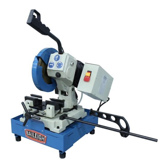
OPERATOR'S MANUAL
MANUAL COLD SAW
MODEL: CS-225M-V2
Baileigh Industrial Holdings LLC
P.O. Box 531
Manitowoc, WI 54221-0531
Phone: 920.684.4990
Fax: 920.684.3944
sales@baileigh.com
REPRODUCTION OF THIS MANUAL IN ANY FORM WITHOUT WRITTEN APPROVAL OF BAILEIGH INDUSTRIAL
HOLDINGS LLC IS PROHIBITED. Baileigh Industrial Holdings LLC, Inc. does not assume and hereby disclaims any
liability for any damage or loss caused by an omission or error in this Operator's Manual, resulting from accident,
negligence, or other occurrence.
Rev. 03/2020
© 2020 Baileigh Industrial Holdings LLC
Advertisement
Table of Contents

Related Manuals for Baileigh CS-225M-V2


Summary of Contents for Baileigh CS-225M-V2
- Page 1 REPRODUCTION OF THIS MANUAL IN ANY FORM WITHOUT WRITTEN APPROVAL OF BAILEIGH INDUSTRIAL HOLDINGS LLC IS PROHIBITED. Baileigh Industrial Holdings LLC, Inc. does not assume and hereby disclaims any liability for any damage or loss caused by an omission or error in this Operator’s Manual, resulting from accident, negligence, or other occurrence.
-
Page 2: Table Of Contents
Table of Contents THANK YOU & WARRANTY ..................1 INTRODUCTION ......................3 GENERAL NOTES ......................3 SAFETY INSTRUCTIONS ....................4 SAFETY PRECAUTIONS ....................6 Dear Valued Customer: ....................6 TECHNICAL SPECIFICATIONS ..................9 TECHNICAL SUPPORT ....................9 UNPACKING AND CHECKING CONTENTS ..............10 TRANSPORTING AND LIFTING .................. -
Page 3: Thank You & Warranty
THANK YOU & WARRANTY Thank you for your purchase of a machine from Baileigh Industrial Holdings LLC. We hope that you find it productive and useful to you for a long time to come. Inspection & Acceptance. Buyer shall inspect all Goods within ten (10) days after receipt thereof. Buyer’s payment shall constitute final acceptance of the Goods and shall act as a waiver of the Buyer’s rights to inspect or... - Page 4 We apologize for any discrepancies that may occur. Baileigh Industrial Holdings LLC reserves the right to make any and all changes deemed necessary in the course of business including but not limited to pricing, product specifications, quantities, and product availability.
-
Page 5: Introduction
INTRODUCTION The quality and reliability of the components assembled on a Baileigh Industrial Holdings LLC machine guarantee near perfect functioning, free from problems, even under the most demanding working conditions. However, if a situation arises, refer to the manual first. If a solution cannot be found, contact the distributor where you purchased our product. -
Page 6: Safety Instructions
IMPORTANT PLEASE READ THIS OPERATORS MANUAL CAREFULLY It contains important safety information, instructions, and necessary operating procedures. The continual observance of these procedures will help increase your production and extend the life of the equipment. SAFETY INSTRUCTIONS LEARN TO RECOGNIZE SAFETY INFORMATION This is the safety alert symbol. - Page 7 SAVE THESE INSTRUCTIONS. Refer to them often and use them to instruct others. PROTECT EYES Wear safety glasses or suitable eye protection when working on or around machinery. PROTECT AGAINST NOISE Prolonged exposure to loud noise can cause impairment or loss of hearing.
-
Page 8: Safety Precautions
Baileigh does not recommend or endorse making any modifications or alterations to a Baileigh machine. Modifications or alterations to a machine may pose a substantial risk of injury to the operator or others and may do substantial damage to the machine. - Page 9 7. Dressing material edges. Always chamfer and deburr all sharp edges. 8. Do not force tool. Your machine will do a better and safer job if used as intended. DO NOT use inappropriate attachments in an attempt to exceed the machines rated capacity. 9.
- Page 10 25. Keep all cords dry, free from grease and oil, and protected from sparks and hot metal. 26. Inspect power and control cables periodically. Replace if damaged or bare wires are exposed. Bare wiring can kill! 27. DO NOT bypass or defeat any safety interlock systems. 28.
-
Page 11: Technical Specifications
(other than die sets and blades). For specific application needs or future machine purchases contact the Sales Department at: sales@baileigh.com, Phone: 920.684.4990, or Fax: 920.684.3944. Note: The photos and illustrations used in this manual are representative only and may not depict the actual color, labeling or accessories and may be intended to illustrate technique only. -
Page 12: Unpacking And Checking Contents
UNPACKING AND CHECKING CONTENTS Your Baileigh machine is shipped complete. Separate all parts from the packing material and check each item carefully. Make certain all items are accounted for before discarding any packing material. WARNING: SUFFOCATION HAZARD! Immediately discard any plastic bags and packing materials to eliminate choking and suffocation hazards to children and animals. - Page 13 Two Person Lift. Use an assistant or lifting devise to support the weight of the saw body. Do not lift alone. Separate all parts from the packing material and check each item carefully. Make certain all items are accounted for before discarding any packing material. Material Stop Rubber Feet Head and Base Assembly...
-
Page 14: Transporting And Lifting
TRANSPORTING AND LIFTING NOTICE: Lifting and carrying operations should be carried out by skilled workers, such as a truck operator, crane operator, etc. If a crane is used to lift the machine, attach the lifting chain carefully, making sure the machine is well balanced. Follow these guidelines when lifting with truck or trolley: •... - Page 15 Positioning the Machine If you intend to mount the Baileigh machine on a workbench be aware of the following: • Position the machine on a solid, level bench capable of supporting the full weight of the machine and the material to be cut.
-
Page 16: Overall Dimensions
OVERALL DIMENSIONS Machine Dimensions (when assembled) -
Page 17: Getting To Know Your Machine
GETTING TO KNOW YOUR MACHINE Saw Blade Head Assembly The section of the machine composed of the motor, gear transfer system, disc or blade, and feed handle. Feed Handle (A) A long angled tube with a grip for raising and lowering the saw blade head and a trigger switch to start and stop the blade motor. -
Page 18: Assembly And Set Up
ASSEMBLY AND SET UP WARNING: For your own safety, DO NOT connect the machine to the power source until the machine is completely assembled and you read and understand the entire instruction manual. Locate and prepare the machine for assembly. 1. - Page 19 7. Attach the feed handle to the head assembly. 8. Insert the threaded end of the feed handle (L) into the gear oil fill hole (M). 9. Turn the handle clockwise (cw) until tight so that the trigger switch (N) points up. 10.
-
Page 20: Electrical
ELECTRICAL CAUTION: HAVE ELECTRICAL UTILITIES CONNECTED TO MACHINE BY A CERTIFIED ELECTRICIAN! Check if the available power supply is the same as listed on the machine nameplate. WARNING: Make sure the grounding wire (green) is properly connected to avoid electric shock. DO NOT switch the position of the green grounding wire if any electrical plug wires are switched during hookup. - Page 21 • Improper connection of the equipment-grounding conductor can result in risk of electric shock. The conductor with insulation having an outer surface that is green with or without yellow stripes is the equipment-grounding conductor. If repair or replacement of the electric cord or plug is necessary, do not connect the equipment-grounding conductor to a live terminal.
-
Page 22: Operation
OPERATION CAUTION: Always wear proper eye protection with side shields, safety footwear, and leather gloves to protect from burrs and sharp edges. When handling large heavy materials, make sure they are properly supported. Miter Angle CAUTION: Check that the cutting blade clears all parts of the vise assembly before cutting. -
Page 23: Loading The Piece Part
Loading the Piece Part 1. Use the vise hand-wheel to open the jaws wider than the width of the piece. 2. Measure and mark off the length of material to be cut. 3. Place the piece on the flat surface in between the vise jaws. 4. -
Page 24: Cutting Operation Cycle
The Baileigh cold saw is now ready to start work. For quality cutting and machine performance always use the correct type of blade or disk and recommended cutting speeds. -
Page 25: Machine Adjustments
MACHINE ADJUSTMENTS WARNING: BEFORE PERFORMING THE FOLLOWING OPERATIONS, THE ELECTRIC POWER SUPPLY AND THE POWER CABLE MUST BE COMPLETELY DISCONNECTED. Setting Saw Blade Head Stop To adjust the saw blade head DOWN stop: 1. Turn the stop bolt (A) up or down as desired to set the stop position of the blade. -
Page 26: Changing The Saw Blade
Changing the Saw Blade To change the saw blade: 1. Loosen the screw (A) enough to rotate the cover plate and expose the hub. Lightly tighten the screw. 2. Release and pivot the mobile guard (B) by removing the hex socket screw (C). 3. -
Page 27: Choosing A Saw Blade
Use the chart on the following page to help select the saw blade suitable for your application. Baileigh Industrial offers a wide selection of tooth styles for various cutting applications. Please phone Baileigh Industrial at (920.684.4990) or fax to (920.684.3944) to have one of our... -
Page 28: Blade Selection Chart
BLADE SELECTION CHART... -
Page 29: Lubrication And Maintenance
LUBRICATION AND MAINTENANCE WARNING: Make sure the electrical disconnect is OFF before working on the machine. Maintenance should be performed on a regular basis by qualified personnel. Always follow proper safety precautions when working on or around any machinery. LUBRICATION OIL TABLE 1 Above 82°F (Select from the products listed below) Brand Hydraulic Tank Oil... - Page 30 Daily Maintenance • Check daily for any unsafe conditions and fix immediately. • Check that all nuts and bolts are properly tightened. • Do a general cleaning by removing dust and metal chips from the machine. • Top off the coolant tank. (80% of full tank capacity) •...
-
Page 31: Accessing And Cleaning The Coolant System
Oils for Lubricating Coolant Any 10:1 (water to coolant) solution will work, however we recommend Baileigh B-Cool 20:1 (water to coolant) biodegradable metal cutting fluid. It has excellent cooling and heat transfer characteristics, is non-flammable, and extends blade and machine life. Each gallon of concentrate makes 21 gallons of coolant. -
Page 32: Parts Diagram
PARTS DIAGRAM... -
Page 34: Parts List
Parts List Item Description Qty. Base Spring Pin Scale Support Block Socket head cap screw Stop Rod Cabinet Coolant tank Hex cap screw Rubber foot Bolt Pipe coupling Coolant tube Disc Swivel Plate Pivot Block Shaft Hex cap screw Socket head cap screw Socket head cap screw Lead Screw Guide rod... - Page 35 Item Description Qty. Socket head cap screw Hex nut Handle hub Handle Spring pin Support Link Lock nut Socket head cap screw Guide link Retaining ring S60 Screw Socket head cap screw Connector fitting Fixed blade guard Moveable blade guide Socket head cap screw Blade shaft flange Blade shaft...
- Page 36 Item Description Qty. Head gasket Switch box Switch Saw Motor Bolt Washer Filter Coolant Motor and Pump Cable Washer Bolt Cover Screw Spring Pin Rubber sheet Front cover plate Cover Stock Stop Bolt Bolt Screw Screw Washer Mounting Plate Blade Washer...
-
Page 37: Electrical Parts
ELECTRICAL PARTS DCPS Electrical Parts List Item Description Technical Data Qty. Power / Emergency Stop 250V / 20A / HY18-XX Trigger Switch 15A 1/2HP 125/250VAC / 0.6A 125VDC Latching Relay CN-6 600VAC 20A RHN-5M 9 – 12.5A Thermal Overload Relay, Coolant Pump JZX-22F(D)/2Z Saw Motor 110V / 60hz 1 HP (.75kw) 10.4A... -
Page 38: Electrical Schematic
ELECTRICAL SCHEMATIC AC110V DC24V+ Coolant Pump DCPS DC POWER DC24V- AC110V Main Motor... -
Page 39: Troubleshooting
TROUBLESHOOTING WARNING: Make sure the electrical disconnect is OFF before working on the machine. Blade and Cut Diagnosis FAULT PROBABLE CAUSE REMEDY Wrong tooth pitch. Choose a suitable disk. DISK VIBRATION Unsuitable tooth profile. Choose a suitable disk. Ineffective gripping of the part in Check the gripping of the part. - Page 40 FAULT PROBABLE CAUSE REMEDY Too fast advance. Decrease advance, exerting less cutting pressure. CUT OFF THE STRAIGHT Ineffective gripping of the part in Check the gripping of the part the vise. which may be moving sideways. Adjust the head. Disk head off the straight. Choose proper tool quality, type, Disk sides differently and construction characteristics.
- Page 41 FAULT PROBABLE CAUSE REMEDY Too fast advance Decrease advance, exerting less cutting pressure. Wrong cutting speed Change disk speed and/or diameter. Wrong tooth pitch Choose a suitable disk. Low quality disk Use a better-quality disk. Ineffective gripping of the part in Check the gripping of the part.
- Page 42 FAULT PROBABLE CAUSE REMEDY Wrong running in of the disk. When cutting for the first time run in the tool, making a series of cuts at a low advance speed, spraying the cutting area with lubricating coolant. Wrong cutting speed. Change disk speed and / or PREMATURE DISK Unsuitable tooth profile.
- Page 43 NOTES...
- Page 44 BAILEIGH INDUSTRIAL HOLDINGS LLC 1625 D , WI 54220 UFEK RIVE ANITOWOC : 920. 684. 4990 F : 920. 684. 3944 HONE www.baileigh.com BAILEIGH INDUSTRIAL HOLDINGS LTD. U WIFT OINT WIFT ALLEY NDUSTRIAL STATE UGBY , CV21 1QH U IDLANDS...
Need help?
Do you have a question about the CS-225M-V2 and is the answer not in the manual?
Questions and answers