Table of Contents
Advertisement
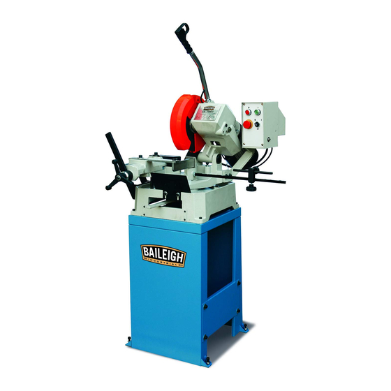
OPERATOR'S MANUAL
MANUAL COLD SAW
MODEL: CS-250EU
Baileigh Industrial Holdings LLC
P.O. Box 531
Manitowoc, WI 54221-0531
Phone: 920.684.4990
Fax: 920.684.3944
sales@baileigh.com
REPRODUCTION OF THIS MANUAL IN ANY FORM WITHOUT WRITTEN APPROVAL OF BAILEIGH INDUSTRIAL
HOLDINGS LLC IS PROHIBITED. Baileigh Industrial Holdings LLC, Inc. does not assume and hereby disclaims any
liability for any damage or loss caused by an omission or error in this Operator's Manual, resulting from accident,
negligence, or other occurrence.
Rev. 04/2020
© 2020 Baileigh Industrial Holdings LLC
Advertisement
Table of Contents

Subscribe to Our Youtube Channel
Related Manuals for Baileigh CS-250EU


Summary of Contents for Baileigh CS-250EU
- Page 1 REPRODUCTION OF THIS MANUAL IN ANY FORM WITHOUT WRITTEN APPROVAL OF BAILEIGH INDUSTRIAL HOLDINGS LLC IS PROHIBITED. Baileigh Industrial Holdings LLC, Inc. does not assume and hereby disclaims any liability for any damage or loss caused by an omission or error in this Operator’s Manual, resulting from accident, negligence, or other occurrence.
-
Page 2: Table Of Contents
Table of Contents THANK YOU & WARRANTY ..................1 INTRODUCTION ......................3 GENERAL NOTES ......................3 SAFETY INSTRUCTIONS ....................4 SAFETY PRECAUTIONS ....................6 Dear Valued Customer: ....................6 TECHNICAL SPECIFICATIONS ..................9 TECHNICAL SUPPORT ....................9 UNPACKING AND CHECKING CONTENTS ..............10 TRANSPORTING AND LIFTING .................. - Page 3 Changing the Saw Blade ................... 33 Blade tracking adjustment ..................34 LUBRICATION AND MAINTENANCE ................35 Accessing and Cleaning the Coolant System ............36 Oils for Lubricating Coolant ..................37 Storing Machine for Extended Period of Time ............37 Cleaning Coolant Path ....................37 LUBRICATION OIL TABLE 1 ..................
-
Page 4: Thank You & Warranty
THANK YOU & WARRANTY Thank you for your purchase of a machine from Baileigh Industrial Holdings LLC. We hope that you find it productive and useful to you for a long time to come. Inspection & Acceptance. Buyer shall inspect all Goods within ten (10) days after receipt thereof. Buyer’s payment shall constitute final acceptance of the Goods and shall act as a waiver of the Buyer’s rights to inspect or... - Page 5 We apologize for any discrepancies that may occur. Baileigh Industrial Holdings LLC reserves the right to make any and all changes deemed necessary in the course of business including but not limited to pricing, product specifications, quantities, and product availability.
-
Page 6: Introduction
INTRODUCTION The quality and reliability of the components assembled on a Baileigh Industrial Holdings LLC machine guarantee near perfect functioning, free from problems, even under the most demanding working conditions. However, if a situation arises, refer to the manual first. If a solution cannot be found, contact the distributor where you purchased our product. -
Page 7: Safety Instructions
IMPORTANT PLEASE READ THIS OPERATORS MANUAL CAREFULLY It contains important safety information, instructions, and necessary operating procedures. The continual observance of these procedures will help increase your production and extend the life of the equipment. SAFETY INSTRUCTIONS LEARN TO RECOGNIZE SAFETY INFORMATION This is the safety alert symbol. - Page 8 SAVE THESE INSTRUCTIONS. Refer to them often and use them to instruct others. PROTECT EYES Wear safety glasses or suitable eye protection when working on or around machinery. PROTECT AGAINST NOISE Prolonged exposure to loud noise can cause impairment or loss of hearing.
-
Page 9: Safety Precautions
Baileigh does not recommend or endorse making any modifications or alterations to a Baileigh machine. Modifications or alterations to a machine may pose a substantial risk of injury to the operator or others and may do substantial damage to the machine. - Page 10 7. Dressing material edges. Always chamfer and deburr all sharp edges. 8. Do not force tool. Your machine will do a better and safer job if used as intended. DO NOT use inappropriate attachments in an attempt to exceed the machines rated capacity. 9.
- Page 11 25. Keep all cords dry, free from grease and oil, and protected from sparks and hot metal. 26. Inspect power and control cables periodically. Replace if damaged or bare wires are exposed. Bare wiring can kill! 27. DO NOT bypass or defeat any safety interlock systems. 28.
-
Page 12: Technical Specifications
(other than die sets and blades). For specific application needs or future machine purchases contact the Sales Department at: sales@baileigh.com, Phone: 920.684.4990, or Fax: 920.684.3944. Note: The photos and illustrations used in this manual are representative only and may not depict the actual color, labeling or accessories and may be intended to illustrate technique only. -
Page 13: Unpacking And Checking Contents
UNPACKING AND CHECKING CONTENTS Your Baileigh machine is shipped complete in two boxes on one pallet. Separate all parts from the packing material and check each item carefully. Make certain all items are accounted for before discarding any packing material. - Page 14 Two Person Lift. Use an assistant or lifting devise (preferred) to support the weight of the saw body. Do not lift alone. Separate all parts from the packing material and check each item carefully. Make certain all items are accounted for before discarding any packing material. Feed Handle Head Assembly Material Stop...
- Page 15 Head Assembly (ref.) 5, 6 5, 6 3, 4 Hardware with Stand Item Description Qty. Socket Bolt M8 x 35mm Rubber Washer Hex Bolt M10 x 40mm Hex Nut M10 Hex Bolt M10 x 20mm Flat washer M10...
-
Page 16: Transporting And Lifting
TRANSPORTING AND LIFTING NOTICE: Lifting and carrying operations should be carried out by skilled workers, such as a truck operator, crane operator, etc. If a crane is used to lift the machine, attach the lifting chain carefully, making sure the machine is well balanced. Follow these guidelines when lifting with truck or trolley: •... -
Page 17: Anchoring The Machine
• Remove scrap and waste materials regularly, and make sure the work area is free from obstructing objects. • If long lengths of material are to be fed into the machine, make sure that they will not extend into any aisles. •... -
Page 18: Overall Dimensions
OVERALL DIMENSIONS Machine Dimensions (when assembled) -
Page 19: Getting To Know Your Machine
GETTING TO KNOW YOUR MACHINE Saw Blade Head Assembly The section of the machine composed of the saw motor, gear case, blade and blade guard, and feed handle and trigger switch. Feed Handle A long angled tube with a grip for raising and lowering the disk head and a trigger switch to start and stop the saw motor. -
Page 20: Vise
Vise A clamping system that provides the basic support and grip for the work material. A handwheel opens and closes the vise jaws. From the operators position in front of the saw, the left side of the vise has the jaws to clamp the material. The right side bar provides support to reduce and prevent the material from kicking out at the end of the cut. -
Page 21: Coolant Pump
Coolant Pump Located within the rear of the machine base is a drawer-like self-contained coolant pump system, and includes a tank, pump, motor, filters, and hose. -
Page 22: Assembly And Set Up
ASSEMBLY AND SET UP WARNING: For your own safety, DO NOT connect the machine to the power source until the machine is completely assembled and you read and understand the entire instruction manual. Prepare the machine for hoisting 1. Using a sling (A), carefully wrap it around the collar of the moveable jaw and motor mount. - Page 23 4. Remove the strap or cord used to hold the head in the lowered position and allow the head to raise to the up position. 5. Remove the oil fill transport plug from gear transfer case. Use a wrench to unscrew an M20x40 hex screw from the oil fill hole (C).
- Page 24 10. Route the switch cord from the handle over the top of the motor to the motor connector box. 11. Locate the socket (G) at the back of the box and plug the connector into the socket and tighten the collar (hand tight) to secure in place.
-
Page 25: Electrical
ELECTRICAL CAUTION: HAVE ELECTRICAL UTILITIES CONNECTED TO MACHINE BY A CERTIFIED ELECTRICIAN! Check if the available power supply is the same as listed on the machine nameplate. WARNING: Make sure the grounding wire (green) is properly connected to avoid electric shock. DO NOT switch the position of the green grounding wire if any electrical plug wires are switched during hookup. - Page 26 • Improper connection of the equipment-grounding conductor can result in risk of electric shock. The conductor with insulation having an outer surface that is green with or without yellow stripes is the equipment-grounding conductor. If repair or replacement of the electric cord or plug is necessary, do not connect the equipment-grounding conductor to a live terminal.
-
Page 27: Operation
OPERATION CAUTION: Always wear proper eye protection with side shields, safety footwear, and leather gloves to protect from burrs and sharp edges. When handling large heavy material make sure they are properly supported. Miter Angle CAUTION: Check that the cutting blade clears all parts of the vise assembly before cutting. -
Page 28: Vise Operation
Vise Operation 1. Use the hand wheel (A) to open and close the vise jaw (B) for pieces that vary in width. a. Counter clockwise (ccw) to open jaws b. Clockwise (cw) to close jaws 2. Use the vise release lever (Z) to quickly clamp and unclamp pieces of the same width. -
Page 29: Using The Stop Bar
Using the stop bar 1. Cut off the first length from the clamped piece part. 2. Unclamp the piece part. 3. Slide the piece part forward until it reaches the tip of the stop bar (C). 4. Clamp the piece part. 5. -
Page 30: Metal Chip Indicators
• Curly Silvery and Warm Chips – optimum feed rate and saw speed The Baileigh cold saw is now ready to start work. For quality cutting and machine performance always use the correct type of blade or disk and recommended cutting speeds. -
Page 31: General Characteristics
General Characteristics Fine Tooth Pitch – used for thin wall materials such as sheet steel, tubes and profiles. Coarse Tooth Pitch – used for large cross-sections, and for soft materials (aluminum alloys and soft alloys in general). Determining Proper Tooth Pitch Proper tooth pitch depends on: The size of the section. -
Page 32: Breaking In A Saw Blade
Breaking in a Saw Blade Important: A new blade requires a break- in period, during which time about half the normal feeding speed should be used. Sharp cutting edges with extremely small edge radii are required for high cutting capacity. To achieve the optimal tool life we recommend breaking-in the blade accordingly. - Page 33 Teeth shape “C” TYPE SHARPENING (HZ) Coarse toothing with roughing tooth raked on both sides and non-raked finishing tooth. The roughing tooth is about 0.3 mm higher. Coarse toothing with roughing tooth and finishing tooth. Used in saws with pitch greater than or equal to 5 mm for cutting ferrous and non-ferrous materials with solid or solid-profiled sections.
- Page 34 Use the chart on the following page to help select the saw blade suitable for your application. Baileigh Industrial offers a wide selection of tooth styles for various cutting applications. Please phone Baileigh Industrial at (920.684.4990) to have one of our technicians assist you in...
-
Page 35: Blade Selection Chart
BLADE SELECTION CHART... -
Page 36: Machine Adjustments
MACHINE ADJUSTMENTS WARNING: BEFORE PERFORMING THE FOLLOWING OPERATIONS, THE ELECTRIC POWER SUPPLY AND THE POWER CABLE MUST BE COMPLETELY DISCONNECTED. Adjustment of Saw Blade Head If excessive axial play is found on the pivot hinge, it will be necessary to tighten the screws. NOTE: Do not overtighten. -
Page 37: Blade Tracking Adjustment
Blade tracking adjustment The head pivot shaft is supported by eccentric bushings. If blade tracks off center resulting in crooked cuts, adjust as follows. 1. Loosen two set screws (A) from rear of head pivot with 4mm hex wrench. 2. If blade tracks to right side (viewed from front of machine), rotate right socket screw (under the electrical box) clockwise with 5mm hex wrench. -
Page 38: Lubrication And Maintenance
LUBRICATION AND MAINTENANCE WARNING: Make sure the electrical disconnect is OFF before working on the machine. Maintenance should be performed on a regular basis by qualified personnel. Always follow proper safety precautions when working on or around any machinery. Daily Maintenance •... -
Page 39: Accessing And Cleaning The Coolant System
Yearly Maintenance Change the oil in the gear case as follows: 1. Lower the saw head to the horizontal (down) position. 2. Disconnect the trigger cord from the electrical box and unscrew the feed handle (A) from the gear case. 3. -
Page 40: Oils For Lubricating Coolant
Oils for Lubricating Coolant Any 10:1 (water to coolant) solution will work, however we recommend Baileigh B-Cool 20:1 (water to coolant) biodegradable metal cutting fluid. It has excellent cooling and heat transfer characteristics, is non-flammable, and extends blade and machine life. Each gallon of concentrate makes 21 gallons of coolant. -
Page 41: Lubrication Oil Table 1
LUBRICATION OIL TABLE 1 Above 82°F (Select from the products listed below) Brand Hydraulic Tank Oil Gear Oil Slideway Oil Mobil DTE XL 68, DTE 16M Mobilgear 634, SHC 460 Mobil Vactra Oil No. 4 Shell Shell Tellus Oil 68 Shell Omala Oil 460 Shell Tonna Oil T220 Exxon... -
Page 42: Electrical Schematic
ELECTRICAL SCHEMATIC Fuse 20A 110V Fuse 20A Fuse 4 Motor 1/8Hp Motor Latching Relay Power Contactor Relay SB1 Emergency Stop Button SB2 Stop Button SB3 Start Button SB4 Trigger Switch SB5 Coolant Pump Switch... -
Page 43: Electrical Parts List
Electrical Parts List Item Description and Function Technical Data Qty. 20A, 10x38 100KA Fuses 20A, 10x38 100KA 2A Gg 10.3x38 Fuse Base 32A 10 x 38 2P 32A 10 x 38 1P Coil 24V, It = 25A, 220V 2.2kw, 400V Contactor 4.0kw, NHD C-09D Relay... -
Page 44: Parts Diagram
PARTS DIAGRAM... -
Page 49: Parts List
Parts List Item Description Size Qty. Lock Handle Hex Socket Cap Screw M10x30 Lock Nut Shaft Spring Washer 5/16" Hex Socket Cap Screw M8x35 Machine Base Plate Counter Weight Filter Net Hex Socket Cap Screw M6x25 Support Rod Roller Shaft Roller Bracket Roller Plate... - Page 50 Item Description Size Qty. Hex Socket Cap Screw Plate Screw M10x30 Spring Washer 1/4" Hex Socket Cap Screw M6x25 Switching Handle Washer 1/4" Hex Socket Cap Screw M6x12 C-Clip Blade Shield Screw M5x10 Plate Rubber Sheet Blade Cover Hex Socket Cap Screw M12x35 Fixing Flange Stopper...
- Page 51 Item Description Size Qty. Oil Seal 25x45x10 Worm Shaft Coupling Motor 1HP Wire Terminal Clamp Control Wire Hex Cap Screw M8x20 Washer 5/16" Screw Cover Bushing Shaft Set Screw PT1/4" Oil Pilot 20m/m Lower Length Setting Rod Upper Length Setting Rod Length Setting Rods Holder Lock Bolt With Knob Lock Bolt With Knob...
- Page 52 Item Description Size Qty. A105 Stop Button A106 Screw A107 Select Switch A108 Pump Selection Switch A109 Control Panel A110 Washer 5/16" A111 Hex Socket Cap Screw M8x20 A112 Electric Control Box A113 Control Box Bottom Plate A114 Magnetic Contactor A115 Fuse Set A116...
-
Page 53: Troubleshooting
TROUBLESHOOTING WARNING: Make sure the electrical disconnect is OFF before working on the machine. Blade and Cut Diagnosis FAULT PROBABLE CAUSE REMEDY Wrong tooth pitch. Choose a suitable disk. DISK VIBRATION Unsuitable tooth profile. Choose a suitable disk. Ineffective gripping of the part in Check the gripping of the part. - Page 54 FAULT PROBABLE CAUSE REMEDY Too fast advance. Decrease advance, exerting less cutting pressure. CUT OFF THE STRAIGHT Ineffective gripping of the part in Check the gripping of the part the vise. which may be moving sideways. Disk head off the straight. Adjust the head.
- Page 55 FAULT PROBABLE CAUSE REMEDY Too fast advance Decrease advance, exerting less cutting pressure. Wrong cutting speed Change disk speed and/or diameter. Wrong tooth pitch Choose a suitable disk. Low quality disk Use a better-quality disk. Ineffective gripping of the part in Check the gripping of the part.
- Page 56 FAULT PROBABLE CAUSE REMEDY Wrong running in of the disk. When cutting for the first time run in the tool, making a series of cuts at a low advance speed, spraying the cutting area with lubricating coolant. Wrong cutting speed. Change disk speed and / or PREMATURE DISK diameter.
- Page 57 NOTES...
- Page 58 NOTES...
- Page 59 NOTES...
- Page 60 BAILEIGH INDUSTRIAL HOLDINGS LLC 1625 D , WI 54220 UFEK RIVE ANITOWOC : 920. 684. 4990 F : 920. 684. 3944 HONE www.baileigh.com BAILEIGH INDUSTRIAL HOLDINGS LTD. U WIFT OINT WIFT ALLEY NDUSTRIAL STATE UGBY , CV21 1QH U IDLANDS...
Need help?
Do you have a question about the CS-250EU and is the answer not in the manual?
Questions and answers