Table of Contents
Advertisement
Quick Links
OPERATOR'S
MANUAL
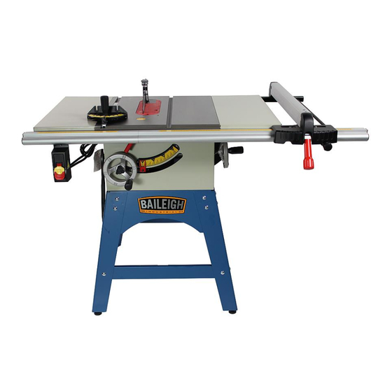
TABLE SAW
MODEL: TS-1040C
Baileigh Industrial, Inc.
P.O. Box 531
Manitowoc, WI 54221-0531
Phone: 920.684.4990
Fax: 920.684.3944
sales@baileigh.com
REPRODUCTION OF THIS MANUAL IN ANY FORM WITHOUT WRITTEN APPROVAL OF BAILEIGH INDUSTRIAL, INC.
IS PROHIBITED. Baileigh Industrial, Inc. does not assume and hereby disclaims any liability for any damage or loss
caused by an omission or error in this Operator's Manual, resulting from accident, negligence, or other occurrence.
Rev. 10/2016
© 2016 Baileigh Industrial, Inc.
Advertisement
Table of Contents

Related Manuals for Baileigh TS-1040C


Summary of Contents for Baileigh TS-1040C
-
Page 1: Table Saw
REPRODUCTION OF THIS MANUAL IN ANY FORM WITHOUT WRITTEN APPROVAL OF BAILEIGH INDUSTRIAL, INC. IS PROHIBITED. Baileigh Industrial, Inc. does not assume and hereby disclaims any liability for any damage or loss caused by an omission or error in this Operator’s Manual, resulting from accident, negligence, or other occurrence. -
Page 2: Table Of Contents
Table of Contents THANK YOU & WARRANTY ..................1 INTRODUCTION ......................3 GENERAL NOTES ......................3 SAFETY INSTRUCTIONS ....................4 SAFETY PRECAUTIONS ....................7 Dear Valued Customer: ....................7 SPECIFICATIONS ......................11 TECHNICAL SUPPORT ....................12 UNPACKING AND CHECKING CONTENTS ..............13 Cleaning ........................ - Page 3 Rabbet Cutting ......................50 Cutting Rabbets with a Dado Blade ................50 Cutting Rabbets with a Standard Blade ..............51 CUTTING TOOLS (OPTIONAL)..................52 Outfeed & Support Tables ..................52 ADJUSTMENT ......................53 Adjusting the 45° & 90° Bevel Stops................53 Adjusting the Bevel Angle Pointer ................
-
Page 4: Thank You & Warranty
THANK YOU & WARRANTY Thank you for your purchase of a machine from Baileigh Industrial. We hope that you find it productive and useful to you for a long time to come. Inspection & Acceptance. Buyer shall inspect all Goods within ten (10) days after receipt thereof. Buyer’s payment shall constitute final acceptance of the Goods and shall act as a waiver of the Buyer’s rights to inspect or... - Page 5 Baileigh Industrial makes every effort to ensure that our posted specifications, images, pricing and product availability are as correct and timely as possible. We apologize for any discrepancies that may occur. Baileigh Industrial reserves the right to make any and all changes deemed necessary in the course of business including but not limited to pricing, product specifications, quantities, and product availability.
-
Page 6: Introduction
After receiving your equipment remove the protective container. Do a complete visual inspection, and if damage is noted, photograph it for insurance claims and contact your carrier at once, requesting inspection. Also, contact Baileigh Industrial and inform them of the unexpected occurrence. Temporarily suspend installation. -
Page 7: Safety Instructions
IMPORTANT PLEASE READ THIS OPERATORS MANUAL CAREFULLY It contains important safety information, instructions, and necessary operating procedures. The continual observance of these procedures will help increase your production and extend the life of the equipment. SAFETY INSTRUCTIONS LEARN TO RECOGNIZE SAFETY INFORMATION This is the safety alert symbol. - Page 8 SAVE THESE INSTRUCTIONS. Refer to them often and use them to instruct others. PROTECT EYES Wear safety glasses or suitable eye protection when working on or around machinery. PROTECT AGAINST NOISE Prolonged exposure to loud noise can cause impairment or loss of hearing.
- Page 9 ROTATING BLADE HAZARD Moving saw blade may result in loss of fingers or limb. DO NOT operate with guard removed. Follow lockout/tagout procedures before servicing. HIGH VOLTAGE USE CAUTION IN HIGH VOLTAGE AREAS. DO NOT assume the power to be off. FOLLOW PROPER LOCKOUT PROCEDURES.
-
Page 10: Safety Precautions
All Baileigh woodworking machines should be used only for their intended use. Baileigh does not recommend or endorse making any modifications or alterations to a Baileigh machine. Modifications or alterations to a machine may pose a substantial risk of injury to the operator or others and may do substantial damage to the machine. - Page 11 1. FOR YOUR OWN SAFETY, READ INSTRUCTION MANUAL BEFORE OPERATING THE MACHINE. Learn the machine’s application and limitations as well as the specific hazards. 2. Only trained and qualified personnel should operate this machine. 3. Make sure guards are in place and in proper working order before operating machinery.
- Page 12 19. Damaged Saw Blades. A damaged saw blade can cause kickback. If in doubt as to the condition of the blade, DO NOT use it. 20. Stay alert. Watch what you are doing and use common sense. DO NOT operate any tool or machine when you are tired.
- Page 13 36. Never leave machine running unattended. TURN POWER OFF. Don’t leave machine until it comes to a complete stop. 37. Make sure machine is disconnected from power supply while motor is being mounted, connected or reconnected. 38. Saw Appropriate Material. Only use this saw for natural wood stock and wood stock products such as particle board, plastics, laminates, and medium-density fiber board (MDF).
-
Page 14: Specifications
SPECIFICATIONS Blade 10” (10” 40T included) Maximum Blade Diameter Riving Knife/Spreader Thickness 0.09 in. (2.3mm) Required Blade Body Thickness 0.078 in. (2mm) Required Blade Kerf Thickness 0.118 in. (3mm) 13/16” (21.6mm) Maximum Width of Dado Blade Tilt Left 0-45 Deg. 5/8”... -
Page 15: Technical Support
(other than die sets and blades). For specific application needs or future machine purchases contact the Sales Department at: sales@baileigh.com, Phone: 920.684.4990, or Fax: 920.684.3944. Note: The photos and illustrations used in this manual are representative only and may not depict the actual color, labeling or accessories and may be intended to illustrate technique only. -
Page 16: Unpacking And Checking Contents
If any parts are missing, DO NOT place the machine into service until the missing parts are obtained and installed correctly. Your Baileigh machine is shipped complete. Separate all parts from the packing material and check each item carefully. Make certain all items are accounted for before discarding any packing material. -
Page 17: Transporting And Lifting
Follow manufacturer’s label instructions when using any type of cleaning product. After cleaning, wipe unpainted metal surfaces with a light coating of quality oil or grease for protection. Important: This waxy coating is NOT a lubricant and will cause the machine to stick and lose performance as the coating continues to dry. -
Page 18: Geting To Know Your Machine
GETING TO KNOW YOUR MACHINE Item Description Item Description Left Front Rail Tube Fence Fine Adjustment Knob Extension Wing Fence Lock Handle Miter Gauge Fence Scale Indicator (use when fence is on left side of blade) Align-A-Cut Marker Blade Tilt Handwheel Blade Guard and Spreader Motor Cover Blade Guard Table Insert... -
Page 19: Installation
INSTALLATION IMPORTANT: Consider the following when looking for a suitable location to place the machine: Overall weight of the machine. Weight of material being processed. Sizes of material to be processed through the machine. Space needed for auxiliary stands, work tables, or other machinery. ... -
Page 20: Assembly
ASSEMBLY WARNING: For your own safety, DO NOT connect the machine to the power source until the machine is completely assembled and you read and understand the entire instruction manual. 1. On a clean surface that will not scratch the finish, lay out two of the stand legs (A) and a short upper panel (B) and a lower support (C). - Page 21 13. With the help of an assistant, place the saw upside down on a clean surface that will not scratch or nick the cast iron table top. 14. Place the stand on the saw so the Baileigh logo faces the same direction as the blade height handwheel.
- Page 22 15. Secure the stand to the table saw body with (4) M8-1.25 x 20 hex bolts, (8) 8mm flat washers, and (4) M8-1.25 hex nuts. 16. With the assistance of two other people, turn the saw upright on its feet. DO NOT ATTEMPT THIS BY YOURSELF! 17.
- Page 23 23. Place the straightedge across the extension wings and main table to make sure that the combined table surface is flat. If the combined table surface is flat, proceed to the next step. If the outside end of the extension wing tilts up or down, you will have to adjust the wings evenly with the table when instructed later in the assembly process.
- Page 24 32. Slide (4) M8-1.25 x 20 T-slot bolts into the slot in the right front rail, then insert the bolts into the mounting holes in the extension wing and main table. 33. Slide the two pins on the end of the right front rail into the holes in the left rail.
- Page 25 Note: The bracket on the back of the fence must be seated below the rear rail for the fence to function correctly. 36. Move the left face of the fence against the blade. 37. While holding the fence stationary, adjust the front rail until the right fence scale zero mark aligns with the centerline on the right fence indicator window.
- Page 26 41. Install the push stick holder with (1) M8-1.25 x 10 hex bolt and flat washer. 42. Slide the fence out of the way. 43. Ensure the blade is raised all the way up and the blade angle is 0°. 44.
-
Page 27: Dust Collection
DUST COLLECTION It is recommended that you use a dust collector (not included) when using this machine. The minimum air flow requirement for this machine are listed below. The machine comes with a 2.5” dust port located on the side of the machine. The dust extraction equipment is to be switched on before commencing machining. -
Page 28: Electrical
ELECTRICAL CAUTION: HAVE ELECTRICAL UTILITIES CONNECTED TO MACHINE BY A CERTIFIED ELECTRICIAN! Check if the available power supply is the same as listed on the machine nameplate. WARNING: Make sure the grounding wire (green) is properly connected to avoid electric shock. DO NOT switch the position of the green grounding wire if any electrical plug wires are switched during hookup. -
Page 29: Power Cord Connection
Improper connection of the equipment-grounding conductor can result in risk of electric shock. The conductor with insulation having an outer surface that is green with or without yellow stripes is the equipment-grounding conductor. If repair or replacement of the electric cord or plug is necessary, do not connect the equipment-grounding conductor to a live terminal. -
Page 30: Controls
CONTROLS ON/OFF Switch: Starts and stops the motor. The switch can be disabled for safety by removing the lockout key. Align-A-Cut Marker: Used to align the cutting mark on the workpiece with the blade kerf. Blade Tilt Handwheel: Adjusts the blade angle from 0°-45°. Micro-Adjustment Knob: Adjusts the fence side-to-side in small increments. -
Page 31: Initial Operation
INITIAL OPERATION WARNING: Before operating; make sure it is positioned firmly on a solid work surface. If it tips over on you, it could cause severe injury or death. Once the assembly is complete, run your machine to make sure it runs properly and is ready for regular operation. -
Page 32: Operation Overview
If the machine DOES start, immediately stop the machine. The switch disabling feature IS NOT working correctly. This safety feature must work properly before proceeding with regular operations. Verify that the lockout key tabs have not broken off and remain in the paddle switch. -
Page 33: Non-Through & Through Cuts
4. Adjusts the fence to the desired width of cut then locks it in place. 5. Checks the outfeed side of the machine for proper support and to make sure the workpiece can safely pass all the way through the blade without interference. 6. -
Page 34: Workpiece Inspection
Workpiece Inspection Some workpieces are not safe to cut on this machine or may need to be modified before they can be safely cut. Before cutting, inspect all workpieces for the following: Material Type: This machine is intended for cutting natural and man-made wood products, laminate covered wood products, and some plastics. -
Page 35: Blade Selection
BLADE SELECTION This section on blade selection is by no means comprehensive. Always follow the saw blade manufacturer's recommendations to ensure safe and efficient operation of your table saw. Ripping Blade Features Best for cutting with the grain 20-40 teeth ... -
Page 36: Dado Blades
Laminate Blade Features Best for cutting plywood or veneer 40-80 teeth Triple chip tooth profile Very shallow gullet Thin Kerf Blade A blade with thinner kerf than a standard blade. Since the spreader/riving knife included with this table saw is sized for standard blades, thin kerf blades cannot be used on this saw unless they meet the Blade Requirements specified in this manual;... -
Page 37: Blade Installation
BLADE INSTALLATION WARNING: Blades are dangerously sharp. Use extreme caution when working with or around the blade. Wear proper safety protection such as heavy gloves. WARNING: Turn the power switch “OFF” and unplug the power cord from its power source when changing the saw blade. When replacing blades, check the thickness stamped onto the riving knife. -
Page 38: Blade Guard Assembly
BLADE GUARD ASSEMBLY The term "blade guard" refers to the assembly that consists of the clear shield, the spreader, and the anti- kickback pawls on each side of the spreader. Each of these components has important safety functions. Guard The clear shield reduces injury risk by providing a barrier around the blade that prevents accidental contact and contains flying wood chips. -
Page 39: Installing Blade Guard & Spreader
Installing Blade Guard & Spreader 1. Disconnect and lockout power to the saw! 2. Remove the table insert. 3. Insert the spreader into the bracket slot and tighten the lock knob to secure the spreader. 4. Tug upward on the top of the spreader to verify it is locked. -
Page 40: Anti-Kickback Pawls
Anti-Kickback Pawls The anti-kickback pawls allow the workpiece to travel in only one direction. If the workpiece moves backwards, such as during a kickback, the pawls will dig into the workpiece to slow or stop it. To work properly, the pawls must freely return to their resting position with contact to the table surface after pivoting. -
Page 41: Riving Knife
Installing Pawls 1. Loosen the knob on top of the spreader, and then remove the blade guard. 2. Slide the pin in the pawl block into the second groove from the front of the spreader. 3. Press the button on the pawl block, and then pivot the pawls down until they lock into place. - Page 42 To ensure that the riving knife works safely, it MUST be aligned with and correctly adjusted to the blade. Check and adjust the riving knife alignment as needed. Place a straightedge against the blade and the spreader. When properly aligned, the spreader/riving knife will be in the "alignment zone,"...
-
Page 43: Cutting A Zero Clearance Insert
Finally, while it may be tempting to use the riving knife for through cutting operations, ALWAYS install the full blade guard and spreader for through cutting. The blade guard and spreader provide more protection from injury and risk reduction than the riving knife. Therefore, we strongly recommend that you use the blade guard assembly instead of the riving knife for through cuts. -
Page 44: Align-A-Cut
8. Turn the saw ON, and then slowly raise the blade to the maximum height that will be used during normal operations. 9. Turn the saw OFF, and lower the blade completely. 10. Remove the board and clamps. 11. Install the blade guard. See "Installing Blade Guard & Spreader". ALIGN-A-CUT The Align-A-Cut marker is an insert on the table top which allows the operator to mark lines which are in line with the kerf of the saw blade being used. -
Page 45: Operation
OPERATION Safety Precautions Before Operations The operation of power tools involves a certain amount of hazard for the operator. Before attempting regular work, we recommend you get the feel of operations using scrap lumber to check settings. Read entire instructions before you start to cut workpiece. Always pay attention to safety precautions to avoid personal injury. -
Page 46: Ripping
Ripping Ripping is the operation of making a lengthwise cut through a board. The rip fence is used to position and guide the workstock. One edge of the workstock rides against the rip fence while the flat side of the board rest on the table. Since the workstock is pushed along the fence, it must have a straight edge and make solid contact with the table. - Page 47 WARNING: Serious injury can be caused by kickback. Kickback is a high-speed ejection of stock from the table saw toward an operator. The operator or bystanders may be struck by flying stock, or the operator's hands can be pulled into the blade during the kickback.
-
Page 48: Miter Ripping
Miter Ripping Miter ripping is performed the same as ripping but with the saw blade set to an angle not perpendicular with the table surface. To tilt the blade to the left, anywhere between 0° and 45°. This is used most often when cutting bevels, compound miters or chamfers. After changing the bevel angle verify the alignment of the guard and splitter;... - Page 49 WARNING: Serious injury can be caused by kickback. Kickback is a high-speed ejection of stock from the table saw toward an operator. The operator or bystanders may be struck by flying stock, or the operator's hands can be pulled into the blade during the kickback.
-
Page 50: Miter Cross Cutting
Miter Cross Cutting This operation is the same as cross cutting, except the miter gauge is set to an angle other than 0. After changing the blade angle, verify the alignment of the guard and splitter and verify that there is clearance with the saw blade. -
Page 51: Cutting Dadoes With A Dado Blade
Various combination of saws and cutters are used to cut grooves from 1/8” to 13/16” for use in shelving, making joints, tenoning, grooving, etc. The cutters are heavily swaged and must be arranged so that this heavy portion falls in the gullet of the outside blades. -
Page 52: Cutting Dadoes With A Standard Blade
Use a sequential process of making multiple, light cuts that get progressively deeper. The actual number of cuts used should be determined by workpiece hardness, total dado depth, and feed rate. In general, if you hear the motor slow down during the cut, you are cutting too deep or feeding too fast. -
Page 53: Rabbet Cutting
5. Set the saw up for the type of cut you need to make, depending on if it is a rip cut or crosscut. 6. Align the blade to cut one of the dado sides. 7. Reconnect the saw to the power source and turn the saw ON. Allow the blade to reach full speed, and then make the cut. -
Page 54: Cutting Rabbets With A Standard Blade
3. Adjust the fence and align the workpiece to perform the cutting operation. 4. Reconnect the saw to the power source and turn the saw ON. When the blade has reached full speed, perform a test cut with a scrap piece of wood. ... -
Page 55: Cutting Tools (Optional)
CUTTING TOOLS (OPTIONAL) Cutting tools such as push sticks (one included with the saw), push blocks, featherboard, crosscut sleds, etc. are extremely useful in providing additional safety as well as added accuracy to your cut. While these types of tools may be purchased, they are often the first projects to be completed when setting up shop. -
Page 56: Adjustment
ADJUSTMENT WARNING: Make sure the electrical disconnect is OFF before working on the machine. Always follow proper safety precautions when working on or around any machinery. Before operation, the machine should be carefully adjusted for best performance. Adjusting the 45° & 90° Bevel Stops 1. -
Page 57: Adjusting The Bevel Angle Pointer
Adjusting the Bevel Angle Pointer The bevel pointer should read “0” when the blade is at 90° to the table. If not, with the blade set 90° vertical to the table, proceed as follows: 1. Disconnect and lockout power to the saw! 2. -
Page 58: Blade Height Adjustment
Blade Height Adjustment CAUTION: To limit your exposure to the blade and maximize the effectiveness of the anti-kickback pawls (when using the riving style splitter & blade guard), never take more blade height than is required to complete the cut. When setting the blade height for through-cuts (cuts all the way through the thickness of a board) set the height of the blade to roughly 1/4"... -
Page 59: Miter Slot To Blade Parallelism
Miter Slot to Blade Parallelism The table saw will provide best results if the miter slot and the rip fence are adjusted parallel to the blade. If either of these is not exactly parallel, your cuts and your finished work will be lower in quality, but more importantly, the risk of kickback will be increased. -
Page 60: Spreader Or Riving Knife Alignment
Spreader or Riving Knife Alignment Checking Alignment The blade guard spreader and riving knife must be aligned with the blade when installed. If the spreader/riving knife is not aligned with the blade, then the workpiece will be forced sideways during the cut, which will increase the risk of kickback. To check the spreader/riving knife alignment: 1. -
Page 61: Fence Adjustments
Adjusting Bent Spreader/Riving Knife 1. Disconnect and lockout power to the saw! 2. Bend the spreader or riving knife by hand while installed, and then follow Steps 1-4 in Checking Alignment to determine if it is parallel with the blade and inside the "Alignment Zone". - Page 62 To adjust the parallelism to the blade: 1. Disconnect and lockout power to the saw! 2. Loosen the two cap screws on the top front of the fence. 3. Unlock the fence; align the left side of the fence with the right edge of the miter slot, then lock the fence.
-
Page 63: Miter Gauge Adjustment
3. Flip your scrap piece of wood over, placing the side that was cut in Step 1 against the fence, and then make your cut. 4. Stop the saw and do not move the fence. 5. Measure the width of the freshly cut workpiece with a tape measure. The workpiece width should be exactly 12". -
Page 64: Maintenance
MAINTENANCE WARNING: Make sure the electrical disconnect is OFF before working on the machine. Maintenance should be performed on a regular basis following proper safety precautions. This table saw requires very little maintenance other than minor lubrication and cleaning. The following sections detail what will need to be done to assure continued operation of your saw. -
Page 65: Cleaning
Cleaning Cleaning the saw is relatively easy. Vacuum excess wood chips and sawdust, and wipe off the remaining dust with a dry cloth. If any resin has built up, use a resin dissolving cleaner to remove it. After cleaning, treat all unpainted cast iron and steel with a non-staining lubricant. Occasionally it will become necessary to clean the internal parts with more than a vacuum. -
Page 66: Lubrication
Lubrication The table saw has sealed lubricated bearings in the motor housing and the arbor assembly, they will not require any additional lubrication. Use a wire brush to clean off the worm gears and trunnions and apply a white lithium grease to keep them lubricated. It is essential to clean components before lubricating them because dust and chips build up on lubricated components and make them hard to move. -
Page 67: Belt Tension & Replacement
BELT TENSION & REPLACEMENT The belt stretches slightly as the saw is used. Most of the stretching will happen during the first 16 hours of use, but it may continue to gradually stretch with continued use and repeated tensioning. Tensioning Belt 1. -
Page 68: Troubleshooting
TROUBLESHOOTING WARNING: Disconnect machine from the power source before attempting any troubleshooting Symptom Possible Cause Possible Solution 1. Switch disabling key removed. 1. Install switch disabling key. 2. Motor connection wired incorrectly. 2. Wire motor correctly (refer to inside 3. Break or short in wiring; or loose junction box cover or manual). - Page 69 Symptom Possible Cause Possible Solution 1. 45 Degree stop bolt is out of 1. Adjust 45 degree stop bolt. Blade does not adjustment. 2. Check for sawdust in trunnions, clean and reach 45 degrees. 2. Sawdust is built up in front trunnion. lubricate as necessary.
-
Page 70: Saw Body Parts Diagram
SAW BODY PARTS DIAGRAM... -
Page 71: Saw Stand Parts Diagram
SAW STAND PARTS DIAGRAM... -
Page 72: Saw Table Parts Diagram
SAW TABLE PARTS DIAGRAM... -
Page 73: Saw Tools Parts Diagram
SAW TOOLS PARTS DIAGRAM... -
Page 74: Saw Parts List
SAW PARTS LIST Item Descriptions Specifications Qty. Fence Cap Screw M6 x 1.0P x 10 Cap Screw M6 x 1.0P x 20 Round Head Screw M5 x 0.8P x 8 Self-Tapping Screw M4 x 1.59P x 8 Round Head Screw M4 x 0.7P x 10 Self-Tapping Screw M4 x 1.59P x 16... - Page 75 Item Descriptions Specifications Qty. Anti-Loose Nut M5 x 0.8P (8B x 6H) Flat Head Screw M5 x 0.8P x 15 Left Side Inner Blade Guard Rod Center Pin Round Head Screw M5 x 0.8P x 6 Bolt Rod Bracket-Left 2.10 Rod Bracket-Right 2.11 Round Head Screw M4 x 0.7P x 10 2.12 Rod Center Pin...
- Page 76 Item Descriptions Specifications Qty. Round Head Screw M5 x 0.8P x 10 Pointer Spacer Fixed Lever 3.10 Shoulder Screw 3.11 Fixed Plate 3.12 Miter Scale Shoulder Screw Wing Extend Table Guide Plate Bolt Table Insert Assembly Cover Iron Plastic Cover Right Wear-Resisting Chip Left Wear-Resisting Chip Left Wear-Chip Double Sided Tape...
- Page 77 Item Descriptions Specifications Qty. Sliding Lever Flat Washer 8.2 x 22 x 3.0t Flat Washer 10 x 25 x 3.0t Hex Screw M10 x 1.5P x 80 Motor Assembly 1.5HP, 110/220V, 60HZ, 1PH, 2P Belt 17-320 V-Belt 125J-6 Set Screw M6 x 1.0P x 10 J-Belt Flat Washer...
- Page 78 Item Descriptions Specifications Qty. Front Rail Right Cover Hex Nut M8 x 1.25P (13B x 6.5H) Square Bolt M8 x 1.25P x 20 Self-Tapping Screw M4 x 1.59P x 12 Fix Shaft Bolt Handle Assembly Spring Retaining Ring ETW-8 Retaining Ring RTW-24 Guide Shaft Lock Knob...
- Page 79 Item Descriptions Specifications Qty. Hex Screw with Washer M8 x 1.25P x 12 (13B x 6.5H) Wrench Mounting Bracket Strain Relief SB8R-1 Self-Tapping Screw M4.5 x 1.81P x 9 Hex Screw M8 x 1.25P x 16 Wrench Mounting Bracket Spring Washer 8.2 x 15.4 Round Head Screw M4 x 0.7P x 10...
- Page 80 Item Descriptions Specifications Qty. Round Head Screw M5 x 0.8P x 30 Square Nut M6 x 1.0P (10B x 5H) Flat Washer 6.2 x 13 x 1.5t Round Head Screw M6 x 1.0P x 12 Magnetic Switch Assembly CSA/UL 123.1 Plastic Screws M4 x 1.59P x 8 123.2 Strain Relief SB8R-3...
- Page 81 NOTES...
- Page 82 NOTES...
- Page 83 NOTES...
- Page 84 , WI 54220 UFEK RIVE ANITOWOC : 920. 684. 4990 F : 920. 684. 3944 HONE BAILEIGH BAILEIGH INDUSTRIAL, INC. 1455 S. C , CA 91761 AMPUS VENUE NTARIO : 920. 684. 4990 F : 920. 684. 3944 HONE BAILEIGH INDUSTRIAL LTD. U...
Need help?
Do you have a question about the TS-1040C and is the answer not in the manual?
Questions and answers