Table of Contents
Advertisement
Quick Links
r e s t r i c t e d
CYSBSYS-RP01
Rap i d I oT C o n n e ct S y ste m o n M o d u l e
Dual band Wi-Fi and Bluetooth®
Description
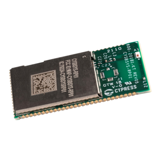
CYSBSYS-RP01 Rapid IoT Connect System on Module (SoM) is the easiest way to provide a secure, scalable, and
reliable connection from your device to your cloud. CYSBSYS-RP01 is a pre-certified 802.11ac-friendly dual-band
(2.4 and 5.0 GHz) Wi-Fi and Bluetooth
with an Arm
®
Cortex
antenna, and passive components. CYSBSYS-RP01 provides up to 51 I/Os in a 26.59 x 14.0 x 2.5 mm castellated
surface-mount PCB for easy manufacturing. CYSBSYS-RP01 is the fastest way to deploy a secure and reliable
network of IoT devices.
Features
• Dual-core PSoC
microcontroller
®
- 150-MHz Arm
®
Cortex
- 100-MHz Cortex-M0+
- 2048-KB Application flash
- 1024-KB SRAM
• Wi-Fi and Bluetooth
- Dual band 2.4 and 5 GHz support
- Simultaneous Wi-Fi and Bluetooth
- 801.11ac-friendly, MCS8 (256-QAM) for 20 MHz channels
- Full IEEE 802.11 a/b/g/n compatibility
- Bluetooth
®
5.0 compliant
- 2 Mbps data rate for Bluetooth
• On-board chip antenna
• Certified to FCC, ISED and CE regulations
• 51 programmable GPIOs
• 73-pin 0.8 mm pitch castellated solder pads SMD package
• Industrial temperature range: -20 °C to 70 °C
• Size: 26.59 mm x 14 mm x 2.5 mm (L x W x H)
• Weight: 2gm
• Pb-free, Halogen-free and RoHS-compliant
Preliminary Datasheet
www.infineon.com
®
5.0-compliant combo radio module. The module includes a PSoC
®
-M4F CPU, and Cortex-M0+ CPU, a single-chip radio, on-board crystals, oscillators, chip
®
-M4F
®
5.0 combo radio
®
operation
Low Energy
®
Please read the Important Notice and Warnings at the end of this document
page 1 of 32
®
6 MCU
002-29368 Rev. *C
2021-08-02
Advertisement
Table of Contents

Related Manuals for Infineon CYSBSYS-RP01


Summary of Contents for Infineon CYSBSYS-RP01
-
Page 1: Description
-M4F CPU, and Cortex-M0+ CPU, a single-chip radio, on-board crystals, oscillators, chip antenna, and passive components. CYSBSYS-RP01 provides up to 51 I/Os in a 26.59 x 14.0 x 2.5 mm castellated surface-mount PCB for easy manufacturing. CYSBSYS-RP01 is the fastest way to deploy a secure and reliable network of IoT devices. -
Page 2: Table Of Contents
r e s t r i c t e d Rapid IoT Connect System on Module Dual band Wi-Fi and Bluetooth® Table of contents Table of contents Description ............................1 Features ............................1 Table of Contents ..........................2 Overview ............................4 Functional block diagram ............................4 ®... - Page 3 r e s t r i c t e d Rapid IoT Connect System on Module Dual band Wi-Fi and Bluetooth® Table of contents Acronyms ............................29 Document conventions ........................30 Revision history ..........................31 Preliminary Datasheet 3 of 32 002-29368 Rev. *C 2021-08-02...
-
Page 4: Overview
Furthermore, it has the diplexer and RF switches required for RF functionality. CYSBSYS-RP01 is a complete hardware solution designed to be soldered to the applications main board. It provides a certified system for customers to design their end solutions. -
Page 5: Dual-Band 802.11Ac-Friendly Radio With Bluetooth ® 5.0
802.11n products when operating in 802.11ac networks. Crystal and oscillators ® The CYSBSYS-RP01 system has an on-board 32.768-kHz oscillator shared between PSoC 6 MCU and the radio. ® The 32.768-kHz oscillator is used by PSoC 6 MCU for the WCO block for Deep sleep operation for low-power-mode timing. -
Page 6: System Connections
This action can also be evoked by an external reset signal, forcing it into a power-on reset state. The XRES signal is an active LOW signal, which is an input to the CYSBSYS-RP01 (ad 49). The CYSBSYS-RP01 module does not require an external pull-up resistor on the XRES input. -
Page 7: Recommended Host Pcb Layout
To maximize performance, the host layout should follow these recommendations: • The ideal placement of the CYSBSYS-RP01 board is in a corner of the host board with the antenna located outside the edge of the host board. This placement minimizes the additional recommended keep out area stated in item 3. -
Page 8: Pin Information
r e s t r i c t e d Rapid IoT Connect System on Module Dual band Wi-Fi and Bluetooth® Pin information Pin information Castellated pads layout P7_0 P6_6 P6_5 P6_7 P6_4 P11_7 VDDIO1 P11_3 P9_1 P11_5 VDDA P11_4 P9_3 P11_6 P9_0... - Page 9 r e s t r i c t e d Rapid IoT Connect System on Module Dual band Wi-Fi and Bluetooth® Pin information Table 1 Pin information Pad number Pad name P5_0 P5_2 VBAT_WL VBAT_WL VDDIO_WL P5_7 P5_3 P5_6 P8_4 P8_0 P8_3 P8_2...
-
Page 10: Castellated Pads Pin Description
P11_2 P6_6 P11_3 P6_7 P11_4 P11_5 P7_0 P11_6 P9_0 P11_7 P9_1 P9_2 P7_3 P9_3 P8_0 P8_1 P9_4 P8_2 P9_7 P8_3 P8_4 P12_6 P12_7 USBDM USBDP CYSBSYS-RP01 Figure 6 Castellated pads pinout Preliminary Datasheet 10 of 32 002-29368 Rev. *C 2021-08-02... - Page 11 Each port pin has multiple alternate functions. These are defined in the table below. The columns ACT #x and DS #y denote active (System LP/ULP) and deep sleep mode signals respectively. Port. Act #0 Act #1 Act #2 Act #3 Act #6 Act #8 #15 DS #5...
- Page 12 Port. Act #0 Act #1 Act #2 Act #3 Act #6 Act #8 #15 DS #5 P5.7 tcpwm[0] tcpwm[1 csd.cs csd.csd_ scb[10]. scb[3].spi .line_- ].line_- d_tx:3 tx_n:37 uart_cts _select3:0 compl[7]: compl[7] P6.0 tcpwm[0] tcpwm[1 csd.cs csd.csd_ scb[8] scb[3].u scb[3]. scb[3].spi cpuss.f scb[8 .line[0]:1...
- Page 13 Port. Act #0 Act #1 Act #2 Act #3 Act #6 Act #8 #15 DS #5 P7.0 tcpwm[0] tcpwm[1 csd.cs csd.csd_ scb[4].u scb[4]. scb[4].spi peri.tr cpuss.t .line[4]:1 ].line[12]: d_tx:4 tx_n:46 art_rx:1 i2c_scl _mosi:1 _io_in race_- put[14] clock P7.3 tcpwm[0] tcpwm[1 csd.cs csd.csd_ scb[4].u...
- Page 14 Port. Act #0 Act #1 Act #2 Act #3 Act #6 Act #8 #15 DS #5 P9.1 tcpwm[0] tcpwm[1 csd.cs csd.csd_ scb[2].u scb[2]. scb[2].spi audios peri.tr cpus .line_- ].line_- d_tx:6 tx_n:63 art_tx:0 i2c_sd _miso:0 s[0].tx _io_in s.tra compl[4]: compl[20 _sck:1 put[19] ce_d ata[...
- Page 15 Port. Act #0 Act #1 Act #2 Act #3 Act #6 Act #8 #15 DS #5 P10.2 tcpwm[0] tcpwm[1 csd.cs csd.csd_ scb[1].u scb[1].spi cpus .line[7]:2 ].line[23]: d_tx:7 tx_n:72 art_rts:1 _clk:1 s.tra ce_d ata[ 1]:1 P10.3 tcpwm[0] tcpwm[1 csd.cs csd.csd_ scb[1].u scb[1].spi cpus .line_-...
- Page 16 Port. Act #0 Act #1 Act #2 Act #3 Act #6 Act #8 #15 DS #5 P11.2 tcpwm[0] tcpwm[1 csd.cs csd.csd_ smif.s scb[5].u scb[5].spi audios .line[2]:3 ].line[2]:1 d_tx:8 tx_n:80 pi_se- art_rts:1 _clk:1 s[1].tx lect0 _ws:1 P11.3 tcpwm[0] tcpwm[1 csd.cs csd.csd_ smif.s scb[5].u scb[5].spi...
-
Page 17: Electrical Specifications
r e s t r i c t e d Rapid IoT Connect System on Module Dual band Wi-Fi and Bluetooth® Electrical specifications Electrical specifications Absolute maximum ratings Table 2 Absolute maximum ratings Parameter Description Units VBAT_WL DC supply voltage for dual-band 802.11ac-friendly radio with -0.5 +5.0 ®... -
Page 18: Recommended Operating Conditions
r e s t r i c t e d Rapid IoT Connect System on Module Dual band Wi-Fi and Bluetooth® Electrical specifications Recommended operating conditions DC specifications Table 3 DC specifications Details / Parameter Description Units conditions VBAT_WL DC supply voltage for dual-band ®... -
Page 19: Rf Parameters
r e s t r i c t e d Rapid IoT Connect System on Module Dual band Wi-Fi and Bluetooth® Electrical specifications RF parameters Wi-Fi radio Table 6 2.4 GHz parameters Parameter Condition Unit Operating Frequency range 4900 5845 Transmit Power 11n, MCS7 17.5... -
Page 20: Power Consumption
r e s t r i c t e d Rapid IoT Connect System on Module Dual band Wi-Fi and Bluetooth® Electrical specifications Power consumption 2.4 GHz WLAN current consumption Table 9 2.4 GHz WLAN current consumption = 3.6V, V = 1.8V, V BAT_WL DDIO_WL... -
Page 21: Environmental Specifications
Dual band Wi-Fi and Bluetooth® Environmental specifications Environmental specifications CYSBSYS-RP01 is built in compliance with the Restriction of Hazardous Substances (RoHS) and Halogen Free (HF) directives. The CYSBSYS-RP01 and components used to produce this module are RoHS- and HF-compliant. RF certification CYSBSYS-RP01 is certified under the following RF certification standards: •... -
Page 22: Regulatory Information
Regulatory information FCC NOTICE The device CYSBSYS-RP01 complies with Part 15 of the FCC Rules. The device meets the requirements for modular transmitter approval as detailed in FCC public Notice DA00-1407. Transmitter Operation is subject to the following two conditions: (1) This device may not cause harmful interference, and (2) This device must accept any interference received, including interference that may cause undesired operation. -
Page 23: Ised
ISED NOTICE The device CYSBSYS-RP01 including the built-in trace antenna complies with Canada RSS-GEN Rules. The device meets the requirements for modular transmitter approval as detailed in RSS-GEN. Operation is subject to the following two conditions: (1) This device may not cause harmful interference, and (2) This device must accept any interference received, including interference that may cause undesired operation. -
Page 24: European Declaration Of Conformity
Annex III of the Directive 2014, the end-customer equipment should be labeled as follows: All versions of the CYSBSYS-RP01 in the specified reference design can be used in the following countries: Austria, Belgium, Cyprus, Czech Republic, Denmark, Estonia, Finland, France, Germany, Greece, Hungary, Ireland, Italy, Latvia, Lithuania, Luxembourg, Malta, Poland, Portugal, Slovakia, Slovenia, Spain, Sweden, The Netherlands, the United Kingdom, Switzerland, and Norway. -
Page 25: Packaging
CYSBSYS-RP01. Preliminary version Figure 7 Tape dimensions Figure 9 details the orientation of CYSBSYS-RP01 in the tape as well as the direction for unreeling. Preliminary version Figure 8 Tape dimensions Preliminary Datasheet 25 of 32 002-29368 Rev. - Page 26 CYSBSYS-RP01. Preliminary version Figure 9 Tape dimensions CYSBSYS-RP01 is designed to be used with pick-and-place equipment in an SMT manufacturing environment. Figure 10 shows the center-of-mass for CYSBSYS-RP01. Preliminary version Figure 10 Center-of-mass for CYSBSYS-RP01...
-
Page 27: Mechanical Dimensions
Rapid IoT Connect System on Module Dual band Wi-Fi and Bluetooth® Mechanical dimensions Mechanical dimensions Physical dimensions of CYSBSYS-RP01 system is as shown in Figure 11 Table 1.00 26.59 1.50 Top View (View from Top) -
Page 28: Ordering Information
MFG Part Number FCC ID ISED ID Unique ID The part numbers are of the form CYSBSYS-RP01 where the fields are defined as follows: CYSBSYS-RP01 Radio type 01 - Dual-band 2.4 GHz/5 GHz radio Marketing code : RP - Rapid IoT Connect Marketing code : SBSYS –... - Page 29 r e s t r i c t e d Rapid IoT Connect System on Module Dual band Wi-Fi and Bluetooth® Acronyms Acronyms Table 18 Acronyms used in this document Acronym Description analog-to-digital converter Cortex ® -M4, an Arm ® CMOS complementary metal-oxide-semiconductor, a process technology for IC fabrication CAPSENSE...
- Page 30 r e s t r i c t e d Rapid IoT Connect System on Module Dual band Wi-Fi and Bluetooth® Document conventions Document conventions Table 19 Unit of measure Symbol Unit of measure °C degrees Celsius decibel decibel-milliwatts hertz 1024 bytes kbps kilobits per second...
- Page 31 r e s t r i c t e d Rapid IoT Connect System on Module Dual band Wi-Fi and Bluetooth® Revision history Revision histor y Document Date of release Description of changes version 2021-08-02 Initial release Preliminary Datasheet 31 of 32 002-29368 Rev.
- Page 32 Infineon Technologies AG With respect to any examples, hints or any typical 81726 Munich, Germany values stated herein and/or any information WARNINGS regarding the application of the product, Infineon Due to technical requirements products may contain Technologies hereby disclaims dangerous substances. For information on the types...
Need help?
Do you have a question about the CYSBSYS-RP01 and is the answer not in the manual?
Questions and answers