Table of Contents
Advertisement
Quick Links
CY8CPROTO-062S2-43439 PSoC™ 62S2 Wi-Fi
Bluetooth® prototyping kit guide
About this document
Scope and purpose
This document serves as a guide for using the CY8CPROTO-062S2-43439 PSoC™ 62S2 Wi-Fi Bluetooth®
prototyping kit. The document explains about the kit contents, design and operation.
Intended audience
This prototyping kit is intended for all technical specialists who are familiar with connectivity and this board is
intended to be used under laboratory conditions.
Reference documents
This user guide should be read in conjunction with the following documents:
AN228571 - Getting started with PSoC™ 6 MCU on ModusToolbox™ software
•
PSoC™ 62 CY8C62x8, CY8C62xA datasheet
•
User Guide
www.infineon.com
Please read the Important Notice and Warnings at the end of this document
page 1 of 34
002-36691 Rev. **
2023-01-25
Advertisement
Table of Contents

Related Manuals for Infineon CY8CPROTO-062S2-43439


Summary of Contents for Infineon CY8CPROTO-062S2-43439
-
Page 1: About This Document
Bluetooth® prototyping kit guide About this document Scope and purpose This document serves as a guide for using the CY8CPROTO-062S2-43439 PSoC™ 62S2 Wi-Fi Bluetooth® prototyping kit. The document explains about the kit contents, design and operation. Intended audience This prototyping kit is intended for all technical specialists who are familiar with connectivity and this board is intended to be used under laboratory conditions. -
Page 2: Table Of Contents
3.2.7 LEDs ..............................27 3.2.8 Push Buttons ............................ 28 3.2.9 Infineon Quad SPI NOR Flash and microSD card ................28 3.2.10 PDM Microphones and Thermistor ....................29 3.2.11 Digilent Pmod™ Headers ........................29 PSoC™ 62S2 Wi-Fi Bluetooth® prototyping board rework ..............30 3.3.1... - Page 3 CY8CPROTO-062S2-43439 PSoC™ 62S2 Wi-Fi Bluetooth® prototyping kit guide Table of contents Bill of Materials ............................30 Frequently Asked Questions ......................... 31 Revision history..........................33 User Guide 3 of 34 002-36691 Rev. ** 2023-01-25...
-
Page 4: Safety And Regulatory Compliance Information
This kit is intended to use for ENGINEERING DEVELOPMENT, DEMONSTRATION, OR EVALUATION PURPOSES ONLY and is not considered by Infineon Semiconductor to be a finished end product fit for general consumer use. It generates, uses, and can radiate radio frequency energy and has not been tested for compliance with the limits of computing devices pursuant to part 15 of FCC or ICES-003 rules, which are designed to provide reasonable protection against radio frequency interference. -
Page 5: General Safety Instructions
General safety instructions ESD protection ESD can damage boards and associated components. Infineon recommends that you perform procedures only at an ESD workstation. If an ESD workstation is unavailable, use appropriate ESD protection by wearing an anti-static wrist strap attached to a grounded metal object. -
Page 6: Introduction
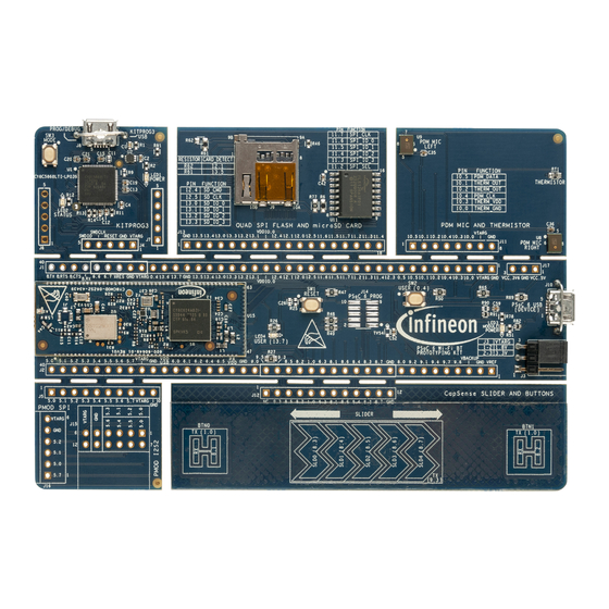
USB Type-A to Micro-B cable • Quick Start Guide (printed on the kit package) • Inspect the contents of the kit; if you find any part missing, contact your nearest Infineon sales office for help: www.infineon.com/support. Board details Figure 1 shows the PSoC™... - Page 7 CY8CPROTO-062S2-43439 PSoC™ 62S2 Wi-Fi Bluetooth® prototyping kit guide Introduction One user LED, a user button, and a reset button for PSoC™ 6 MCU • One Mode selection button and one Mode LED for KitProg3 • Figure 1 Board components User Guide 7 of 34 002-36691 Rev.
- Page 8 CY8CPROTO-062S2-43439 PSoC™ 62S2 Wi-Fi Bluetooth® prototyping kit guide Introduction Figure 2 Prototyping board pinout Table 1 Board pinout PSoC™ 6 MCU Primary onboard function Secondary onboard Connection details function XRES Hardware Reset – Remove R47 to disconnect it from KitProg3 reset.
- Page 9 CY8CPROTO-062S2-43439 PSoC™ 62S2 Wi-Fi Bluetooth® prototyping kit guide Introduction PSoC™ 6 MCU Primary onboard function Secondary onboard Connection details function P1.0 CAPSENSE™ Button TX GPIO Connected to CAPSENSE™ by default. Remove R35 to disconnect CAPSENSE™. P5.0 UART RX MCLK To use PMOD, Remove R72 to disconnect from KitProg3 UART TX.
- Page 10 CY8CPROTO-062S2-43439 PSoC™ 62S2 Wi-Fi Bluetooth® prototyping kit guide Introduction PSoC™ 6 MCU Primary onboard function Secondary onboard Connection details function P8.3 CAPSENSE™ Silder0 Rx GPIO Connected to CAPSENSE™ by default. Remove R40 to disconnect CAPSENSE™. P8.4 CAPSENSE™ Silder1 Rx GPIO Connected to CAPSENSE™...
- Page 11 CY8CPROTO-062S2-43439 PSoC™ 62S2 Wi-Fi Bluetooth® prototyping kit guide Introduction PSoC™ 6 MCU Primary onboard function Secondary onboard Connection details function P11.5 QSPI FLASH DATA1 – – P11.6 QSPI FLASH DATA0 – – P11.7 QSPI FLASH CLK – – P12.0 GPIO –...
-
Page 12: Getting Started
CY8CPROTO-062S2-43439 PSoC™ 62S2 Wi-Fi Bluetooth® prototyping kit guide Introduction Getting started This guide will help you to get acquainted with the PSoC™ 62S2 Wi-Fi Bluetooth® prototyping kit: PSoC™ 62S2 Wi-Fi Bluetooth® prototyping kit requires ModusToolbox™ 3.0 to design and debug applications. -
Page 13: Documentation Conventions
CY8CPROTO-062S2-43439 PSoC™ 62S2 Wi-Fi Bluetooth® prototyping kit guide Introduction Documentation conventions Table 2 Document conventions for guides Convention Usage Courier New Displays user-entered text and source code Italics Displays file names and reference documentation: Read about the sourcefile.hex file in the PSoC™ Creator user guide. - Page 14 CY8CPROTO-062S2-43439 PSoC™ 62S2 Wi-Fi Bluetooth® prototyping kit guide Introduction Abbreviation Definition Integrated Circuit ICSP In-Circuit Serial Programming IDAC Current Digital-to-Analog Converter Integrated Development Environment Internet of Things Light-emitting Diode Low Power Oscillator Out Of Box Personal Computer Peripheral Driver Library...
-
Page 15: Kit Operation
CY8CPROTO-062S2-43439 PSoC™ 62S2 Wi-Fi Bluetooth® prototyping kit guide Kit operation Kit operation This chapter introduces you to various features of the PSoC™ 62S2 Wi-Fi Bluetooth® prototyping kit, including the theory of operation and the onboard programming and debugging functionality, KitProg3 USB-UART and USB-I2C bridges. - Page 16 CY8CPROTO-062S2-43439 PSoC™ 62S2 Wi-Fi Bluetooth® prototyping kit guide Kit operation The PSoC™ 62S2 Wi-Fi Bluetooth® prototyping board consists of multiple sections, a KitProg3 section, PSoC™ 6 MCU section and other peripheral sections. An on-board programmer, KitProg3 is used to program and debug the target PSoC™...
- Page 17 MCU pin mapping, see Table Infineon PSoC™ 6 Wi-Fi BT Module (CY8CMOD-062S2-43439, U1): This kit is designed to highlight the features of the PSoC™ 6 MCU on the CY8CMOD-062S2-43439. For details on see the module datasheet. CYW43439 based Murata 1YN Module: The Type 1YN is a small and high-performance module which supports Wi-Fi 802.11b/g/n + Bluetooth®...
-
Page 18: Kitprog3
PSoC™ 5LP and PSoC™ 6 MCU respectively. Infineon 512-Mbit serial NOR flash memory (S25HL512T, U11): The S25HL512T NOR flash of 512Mb capacity is connected to the serial memory interface (SMIF) of the PSoC™ 6 MCU. The NOR flash can be used for both data and code memory with execute-in-place (XIP) support and encryption. - Page 19 CY8CPROTO-062S2-43439 PSoC™ 62S2 Wi-Fi Bluetooth® prototyping kit guide Kit operation Figure 6 Connect USB cable to USB connector on the board In the ModusToolbox™ IDE, import the desired application into a new workspace. If you aren’t familiar with this process, see KBA225201.
-
Page 20: Using Oob Example
CY8CPROTO-062S2-43439 PSoC™ 62S2 Wi-Fi Bluetooth® prototyping kit guide Kit operation ModusToolbox™ has an integrated debugger. To debug a PSoC™ 6 MCU application, in the Project Explorer, select <App_Name> project. In the Quick Panel, scroll to the Launches section and click the <App_Name>... -
Page 21: Usb-I2C Bridge
CY8CPROTO-062S2-43439 PSoC™ 62S2 Wi-Fi Bluetooth® prototyping kit guide Kit operation 2.2.4 USB-I2C Bridge The onboard KitProg3 also functions as a USB-I2C bridge, for example, to communicate with the CAPSENSE™ Tuner. The I2C lines on the PSoC™ 6 MCU are hard-wired on the board to the I2C lines of the KitProg3 with... -
Page 22: Hardware
3.2.1 CY8CMOD-062S2-43439 (U15) The Infineon CY8CMOD-062S2-43439 is a pre-certified module supporting 2.4 GHz WLAN and Bluetooth® functionality. The CY8CMOD-062S2-43439 module is a turnkey solution and includes PSoC™ 6 MCU, CYW43439 Single-Chip radio, onboard oscillators, chip antenna and passive components. The CY8CMOD-062S2-43439 module provides up to 80 I/Os of PSoC™... -
Page 23: Psoc™ 5Lp (U1)
CY8CPROTO-062S2-43439 PSoC™ 62S2 Wi-Fi Bluetooth® prototyping kit guide Hardware 3.2.2 PSoC™ 5LP (U1) An onboard PSoC™ 5LP (CY8C5868LTI-LP039) is used as a KitProg3 to program and debug the PSoC™ 6 MCU. The PSoC™ 5LP is a bridge between the USB port of a PC and the SWD and other communication interfaces of the PSoC™... -
Page 24: Serial Interconnection Between Psoc™ 5Lp And Psoc™ 6 Mcu
CY8CPROTO-062S2-43439 PSoC™ 62S2 Wi-Fi Bluetooth® prototyping kit guide Hardware 3.2.3 Serial interconnection between PSoC™ 5LP and PSoC™ 6 MCU The PSoC™ 5LP functions as USB-UART and USB-I2C bridge as shown in Figure The USB-Serial pins of the PSoC™ 5LP are hard-wired to the I2C/UART pins of the PSoC™ 6 MCU. These pins are also available on the breadboard-compatible I/O headers. -
Page 25: Power Supply System
CY8CPROTO-062S2-43439 PSoC™ 62S2 Wi-Fi Bluetooth® prototyping kit guide Hardware 3.2.4 Power supply system The power supply system on this board allows the input supply to come from the following sources: 5 V from the onboard USB Micro-B connectors (J8 and J10) •... -
Page 26: Expansion Connectors
CY8CPROTO-062S2-43439 PSoC™ 62S2 Wi-Fi Bluetooth® prototyping kit guide Hardware 3.2.5 Expansion connectors 3.2.5.1 PSoC™ 6 MCU I/O Headers (J1 and J2) These headers provide connectivity to PSoC™ 6 MCU GPIOs. Most of these pins are multiplexed with onboard peripherals. Figure 15 Schematics of PSoC™... -
Page 27: Capsense™ Circuit
CY8CPROTO-062S2-43439 PSoC™ 62S2 Wi-Fi Bluetooth® prototyping kit guide Hardware 3.2.6 CAPSENSE™ circuit There is a CAPSENSE™ slider and two buttons, all of which support both self-capacitance (CSD) and mutual- capacitance (CSX) sensing. These are connected to the PSoC™ 6 MCU as Figure 17 shows. -
Page 28: Push Buttons
Figure 19 Schematics of Push Buttons 3.2.9 Infineon Quad SPI NOR Flash and microSD card The board has a Infineon NOR Flash memory (S25FL512SAGMFI010) of 512 Mbit capacity. The NOR Flash is connected to the serial memory interface (SMIF) of the PSoC™ 6 MCU. The NOR Flash device can be used for both data and code memory with execute-in-place (XIP) support and encryption. -
Page 29: Pdm Microphones And Thermistor
CY8CPROTO-062S2-43439 PSoC™ 62S2 Wi-Fi Bluetooth® prototyping kit guide Hardware 3.2.10 PDM Microphones and Thermistor The board includes two PDM Microphones (U8 and U9) and a thermistor (RT1) connected to the PSoC™ 6 MCU device. The PDM mics share the same clock and data lines and one is configured on the left channel and the other on the right channel. -
Page 30: Psoc™ 62S2 Wi-Fi Bluetooth® Prototyping Board Rework
CY8CPROTO-062S2-43439 PSoC™ 62S2 Wi-Fi Bluetooth® prototyping kit guide Hardware PSoC™ 62S2 Wi-Fi Bluetooth® prototyping board rework This section explains modifications that can be made to the board to evaluate different use cases. 3.3.1 CAPSENSE™ Shield The hatched pattern around the CAPSENSE™ buttons and slider are connected to ground. In case liquid tolerance is required, this pattern needs to be connected to the shield pin. - Page 31 Ensure that target device used in the ModusToolbox™ application is CY8C624ABZI-S2D44. Does the board get powered when I power it from another Infineon kit through the J17 header? Yes, VCC_5V pin on J17 header is a supply input/output pin and can take up to 5.5 V.
- Page 32 CY8CPROTO-062S2-43439 PSoC™ 62S2 Wi-Fi Bluetooth® prototyping kit guide Hardware What is Pmod? Pmod interface or Peripheral Module interface is an open standard defined by Digilent Inc. in the Digilent Pmod Interface Specification for peripherals used with FPGAs or microcontrollers. Several types of modules are available from simple push buttons to more complex modules with network interfaces, analog to digital converters or LCD displays.
- Page 33 CY8CPROTO-062S2-43439 PSoC™ 62S2 Wi-Fi Bluetooth® prototyping kit guide Revision history Revision history Major changes since the last revision Date Version Description 2023-02-01 New kit guide. User Guide 33 of 34 002-36691 Rev. ** 2023-01-25...
- Page 34 With respect to any examples, hints or any typical WARNINGS values stated herein and/or any information 81726 Munich, Germany regarding the application of the product, Infineon Due to technical requirements products may contain Technologies hereby disclaims any and all dangerous substances. For information on the types...
Need help?
Do you have a question about the CY8CPROTO-062S2-43439 and is the answer not in the manual?
Questions and answers