Table of Contents
Advertisement
Quick Links
CY4534 EZ-PD™ barrel connector replacement-
plus (BCR-PLUS) evaluation kit guide
About this document
Scope and purpose
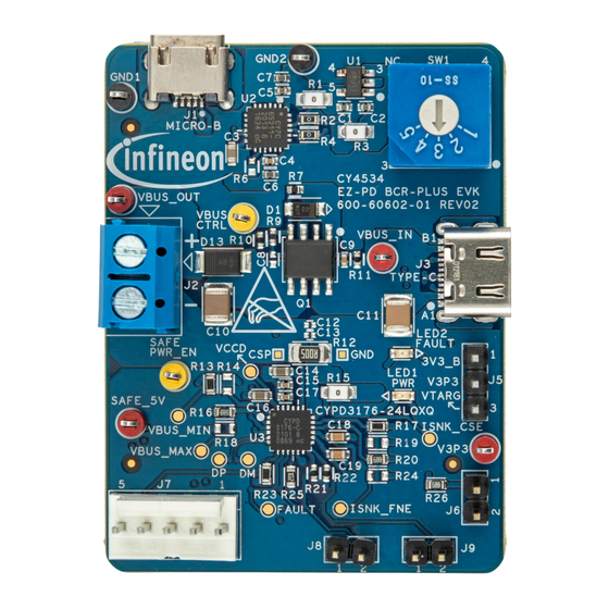
The CY4534 EZ-PD™ barrel connector replacement plus (BCR-PLUS) evaluation kit (EVK) is based on the
CYPD3176 device which is part of the BCR product family of Infineon's USB Type-C and power delivery
controllers. This document serves as the user guide for this CY4534 EZ-PD™ BCR-PLUS EVK.
Intended audience
This EVK is primarily intended for Infineon's USB Type-C customers who want an evaluation platform to replace
an existing barrel/power input connector with a USB-C connector.
Abbreviations and definitions
Table 1
Abbreviations
Abbreviation
AFC
BC
BCR
CC
CCG
DFP
DNP
EC
EMCA
ESD
EVK
FET
GPIO
HPI
IC
2
I
C
LED
NA
OVP
PA
PD
PDO
PFET
User Guide
www.infineon.com
Definition
adaptive fast charging
battery charging
barrel connector replacement
configuration channel
cable controller generation
downstream facing port
do not populate
embedded controller
electronically marked cable assembly
electrostatic discharge
evaluation kit
field-effect transistor
general-purpose input/ output
host processor interface
integrated circuit
inter-integrated circuit
light-emitting diode
not applicable
over voltage protection
power adapter
power delivery
power data object
P-channel field effect transistor
Please read the Important Notice and Warnings at the end of this document
page 1 of 26
002-34123 Rev. **
2021-10-21
Advertisement
Table of Contents

Related Manuals for Infineon EZ-PD CY4534


Summary of Contents for Infineon EZ-PD CY4534
-
Page 1: About This Document
The CY4534 EZ-PD™ barrel connector replacement plus (BCR-PLUS) evaluation kit (EVK) is based on the CYPD3176 device which is part of the BCR product family of Infineon’s USB Type-C and power delivery controllers. This document serves as the user guide for this CY4534 EZ-PD™ BCR-PLUS EVK. - Page 2 CY4534 EZ-PD™ barrel connector replacement-plus (BCR-PLUS) evaluation kit guide About this document Abbreviation Definition programmable system-on-chip ™ PSoC Qualcomm quick charge ® software development kit system-on-chip upstream facing port universal serial bus USB-PD universal serial bus power delivery under voltage protection User Guide 2 of 26 002-34123 Rev.
-
Page 3: Safety Information
General safety instructions ESD protection ESD can damage boards and associated components. Infineon recommends that the user perform procedures only at an ESD workstation. If an ESD workstation is not available, use appropriate ESD protection by wearing an antistatic wrist strap attached to the chassis ground (any unpainted metal surface) on the board when handling parts. -
Page 4: Table Of Contents
CY4534 EZ-PD™ barrel connector replacement-plus (BCR-PLUS) evaluation kit guide Table of contents Table of contents About this document ........................1 Safety information ......................... 3 Table of contents ..........................4 Introduction .......................... 5 Kit contents ............................. 5 Hardware not included with the kit ......................5 Getting started............................ -
Page 5: Introduction
The CY4534 EZ-PD™ barrel connector replacement plus (BCR-PLUS) evaluation kit (EVK) is based on the CYPD3176 device which is part of the BCR product family of Infineon’s USB Type-C and power delivery controllers. This EVK is intended to be an evaluation vehicle for customers who want to replace an existing barrel/power input connector with a USB-C connector. -
Page 6: Hardware
This part manages the USB Type-C port and controls the load switch (PFET). USB-I2C bridge controller Infineon’s USB-serial part (CY7C65211-24LTXI) is connected to the USB micro-B connector (J1) of the EVK. This part works as a USB-I2C bridge for downloading firmware and configuring the BCR-PLUS device using the EZ-PD™... -
Page 7: Bcr System Overview
CY4534 EZ-PD™ barrel connector replacement-plus (BCR-PLUS) evaluation kit guide Hardware REFDES Component Description “DC_OUT” terminal block Terminal block to measure the output voltage of the EVK or to connect any external electronic load. Type-C connector A power-only USB Type-C connector with D+/D-. Alternate power selection Power selection jumper to select the alternate power to supply jumper... - Page 8 CY4534 EZ-PD™ barrel connector replacement-plus (BCR-PLUS) evaluation kit guide Hardware Figure 2 Typical electronic device and its DC barrel power adapter Such electronic devices usually require a specific voltage and current output from the power adapter. To satisfy this, the DC barrel adapter’s plug is often custom-made for a device. USB was the first connector to introduce a standard method of supplying 7.5-W power at 5 V to electronic devices.
-
Page 9: Block Diagram And Functional Description
CY4534 EZ-PD™ barrel connector replacement-plus (BCR-PLUS) evaluation kit guide Hardware DEVICE USB-C AC SOCKET CHARGER USB-C CABLE CY4534 Figure 4 Using the CY4534 EZ-PD™ BCR-PLUS EVK to convert USB Type-C power adapter to legacy barrel adapter Block diagram and functional description Figure 5 shows the block diagram of the CY4534 EZ-PD™... -
Page 10: Ez-Pd™ Bcr-Plus Controller Features
CY4534 EZ-PD™ barrel connector replacement-plus (BCR-PLUS) evaluation kit guide Hardware The EZ-PD™ BCR-PLUS controller supports an I C bootloader for downloading firmware or updating the configuration parameters of the configuration table using the EZ-PD™ configuration utility. The CY4534 EZ-PD™ BCR-PLUS EVK features an on-board BCR-PLUS controller which communicates with a USB Type-C power adapter to negotiate for the proper voltage and current, as specified by on-board resistors. -
Page 11: Vbus Voltage And Current Selectors
CY4534 EZ-PD™ barrel connector replacement-plus (BCR-PLUS) evaluation kit guide Hardware Power supplied by the USB Type-C power adapter is sent to an external device or load through a set of back-to- back power PMOSFETs. The PMOSFETs are used for the following functions: Reduce the in-rush current due to large capacitive loads. - Page 12 CY4534 EZ-PD™ barrel connector replacement-plus (BCR-PLUS) evaluation kit guide Hardware Table 3 for a complete list of the available pull-up and pull-down resistor values. Table 3 Resistor divider values for achieving the desired VBUS_MIN and VBUS_MAX voltages Voltage on VBUS_MAX or Correlated VBUS Pull-up resistor value Pull-down resistor value...
-
Page 13: Fault Led And Vbus-Powered Led
CY4534 EZ-PD™ barrel connector replacement-plus (BCR-PLUS) evaluation kit guide Hardware 2.3.4 Fault LED and VBUS-powered LED Figure 8 Red FAULT LED and green VBUS-powered LED The fault LED will be turned on by driving the FAULT pin HIGH under the following conditions: A USB-PD contract could not be negotiated and the VBUS_MIN voltage indicated is not 5 V. -
Page 14: External Host Processor Interface (Hpi) Connection Header
CY4534 EZ-PD™ barrel connector replacement-plus (BCR-PLUS) evaluation kit guide Hardware Before using the EZ-PD™ configuration utility for updating the configuration parameters of the BCR-PLUS device on EVK board, the alternate power selection jumper (J5) should be placed at position 1-2. In addition to that, the USB Type-C connector (J3) should be left unconnected and the USB Micro-B connector (J1) should be connected to the PC (which has the EZ-PD™... -
Page 15: Changing The Vbus Voltage And Current Requested From The Power Adapter
CY4534 EZ-PD™ barrel connector replacement-plus (BCR-PLUS) evaluation kit guide Hardware Changing the VBUS voltage and current requested from the power adapter The BCR-PLUS device executes a capability matching algorithm to select the best voltage and current from the attached USB Type-C power adapter. Internally, the BCR-PLUS device maintains a ‘Sink Capabilities’... -
Page 16: Kit Operation
CY4534 EZ-PD™ barrel connector replacement-plus (BCR-PLUS) evaluation kit guide Kit operation Kit operation This chapter describes how to configure the CY4534 EZ-PD™ BCR-PLUS EVK to demonstrate the functionality as a USB Type-C power sink attached to an external device or load. External hardware required for demos A USB Type-C power adapter or power bank device •... -
Page 17: Demo #2: Change The Sink Capabilities From The Ez-Pd™ Configuration Utility
CY4534 EZ-PD™ barrel connector replacement-plus (BCR-PLUS) evaluation kit guide Kit operation To set up the demo, perform the following steps: 1. Connect a multimeter to the DC_OUT terminal block (J2) of the CY4534 EZ-PD™ BCR-PLUS EVK. If desired, you may also have a load connected in parallel with the multimeter. See Board details to determine the polarity of the terminal block or look at the markings on the back of the board. - Page 18 CY4534 EZ-PD™ barrel connector replacement-plus (BCR-PLUS) evaluation kit guide Kit operation Micro-B BCR- PLUS 2 3 4 Figure 13 Configuring the BCR-PLUS device on the CY4534 EZ-PD™ BCR-PLUS EVK To set up the demo as shown in Figure 13, perform the following steps: 1.
- Page 19 CY4534 EZ-PD™ barrel connector replacement-plus (BCR-PLUS) evaluation kit guide Kit operation Figure 15 Read existing configuration parameters 7. The existing configuration parameters will be displayed. Before proceeding further, save this default configuration on your PC so that you can reload it once you are done with this demo. 8.
- Page 20 CY4534 EZ-PD™ barrel connector replacement-plus (BCR-PLUS) evaluation kit guide Kit operation Figure 17 Removing the sink variable PDO#2 from the configuration table 10. Save your project on your PC to a different file than the default configuration that you saved earlier. 11.
- Page 21 CY4534 EZ-PD™ barrel connector replacement-plus (BCR-PLUS) evaluation kit guide Kit operation Figure 18 Configure the BCR-PLUS device using the EZ-PD™ configuration utility 14. After programming is complete, recycle power to the EVK board by disconnecting and re-connecting the USB micro-B cable from the EVK board. 15.
-
Page 22: 3.2.3 Demo #3: Test With Legacy Charging Mode Feature
CY4534 EZ-PD™ barrel connector replacement-plus (BCR-PLUS) evaluation kit guide Kit operation 3.2.3 Demo #3: Test with legacy charging mode feature The CY4534 EZ-PD™ BCR-PLUS EVK ships with pre-programmed firmware supported to enable or disable the Legacy charging protocol by changing the jumper J6’s setting for the CHARGING_MODE pin. For details, refer to Legacy charging mode selection jumper section. -
Page 23: Evk Behavior Under Mismatched Capabilities
CY4534 EZ-PD™ barrel connector replacement-plus (BCR-PLUS) evaluation kit guide Kit operation 7. Short J6 pin 1 and pin 2 to disable the legacy charging support for all protocols other than BC1.2 for the BCR-PLUS device. 8. Set the VBUS_MAX rotary switch (SW1) to position 1. Reconnect the power adapter using the USB-A to Type- C cable. -
Page 24: Terminology
CY4534 EZ-PD™ barrel connector replacement-plus (BCR-PLUS) evaluation kit guide Terminology Terminology This guide assumes that you are familiar with the fundamentals of the Type-C connectivity and the USB power delivery protocol. A brief description of Type-C terms is provided here for reference. Alternate modes: A feature of a USB Type-C system whereby one or both SuperSpeed lanes may be •... -
Page 25: Revision History
CY4534 EZ-PD™ barrel connector replacement-plus (BCR-PLUS) evaluation kit guide Revision history Revision history Date Version Description 2021-10-21 Initial release User Guide 25 of 26 002-34123 Rev. ** 2021-10-21... - Page 26 With respect to any examples, hints or any typical WARNINGS values stated herein and/or any information 81726 Munich, Germany regarding the application of the product, Infineon Due to technical requirements products may contain Technologies hereby disclaims any and all dangerous substances. For information on the types...
Need help?
Do you have a question about the EZ-PD CY4534 and is the answer not in the manual?
Questions and answers