
Related Manuals for Extreme Networks ReachNXT 100-8t


Summary of Contents for Extreme Networks ReachNXT 100-8t
- Page 1 ™ ReachNXT 100-8t User Guide Extreme Networks, Inc. 3585 Monroe Street Santa Clara, California 95051 (888) 257-3000 (408) 579-2800 http://www.extremenetworks.com Published: February 2009 Part Number: 120489-00 Rev. 01...
- Page 2 Extreme Networks logo, the Alpine logo, the BlackDiamond logo, the Extreme Turbodrive logo, the Summit logos, and the Powered by ExtremeXOS logo are trademarks or registered trademarks of Extreme Networks, Inc. or its subsidiaries in the United States and/or other countries.
-
Page 3: Table Of Contents
Contents Chapter 1: Overview of the ReachNXT 100-8t Port Extender... 5 About the ReachNXT 100-8t Port Extender...5 ExtremeXOS Interoperability...6 Power over Ethernet (PoE) Support ...6 Monitoring the ReachNXT 100-8t ...7 Upgrading Firmware on the ReachNXT 100-8t ...7 ReachNXT 100-8t Front Panel ...7 ReachNXT 100-8t Rear Panel ...9... - Page 4 SFP (Mini-GBIC), XENPAK, and XFP Regulatory Compliance ...27 Appendix B: Technical Specifications ... 33 ReachNXT 100-8t User Guide...
-
Page 5: Chapter 1: Overview Of The Reachnxt 100-8T Port Extender
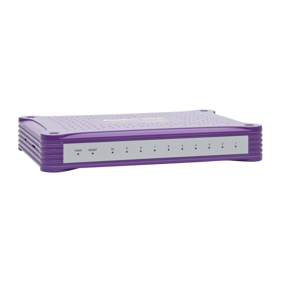
● About the ReachNXT 100-8t Port Extender The ReachNXT 100-8t port extender is an 8-port 10/100 switch with Gigabit uplink capability. It features eight 10/100BASE-T ports for user access and one combination Gigabit Ethernet uplink port, which connects to a switch running ExtremeXOS software. -
Page 6: Extremexos Interoperability
100-8t (port 9) to a port on the uplinked ExtremeXOS switch, and enable inline power for the port on the uplinked switch. NOTE If you are using the SFP uplink port to connect the ReachNXT 100-8t to the uplinked ExtremeXOS switch, you must power the ReachNXT 100-8t using AC power. Support for ReachNXT 100-8t... -
Page 7: Monitoring The Reachnxt 100-8T
Monitoring the ReachNXT 100-8t When the ReachNXT 100-8t is operational, it is visible in your network either from the uplinked ExtremeXOS switch or using EPICenter network management software. The ReachNXT 100-8t sends LLDP Data Units (LLDPDUs) to the uplinked switch every 30 seconds. The LLDPDUs contain type-length-value elements (TLVs) for Chassis ID, Port ID, TTL, System Name, and System Description. - Page 8 Operating on PoE power. No power. Firmware upgrade in progress. Diagnostics have failed. Diagnostics are in progress. ReachNXT 100-8t is initialized and connected to an ExtremeXOS switch. ReachNXT 100-8t is not connected to an ExtremeXOS switch. Link is OK. Port is transmitting packets.
-
Page 9: Reachnxt 100-8T Rear Panel
For more information about SFPs, see the Extreme Networks Pluggable Interface Modules Installation Guide. AC power input socket ● The AC power adapter used with the ReachNXT 100-8t is model number IU18-2120125-WP from Leader Electronics, Inc. Reset button ● Slot for attaching a Kensington lock ●... - Page 10 Overview of the ReachNXT 100-8t Port Extender ReachNXT 100-8t User Guide...
-
Page 11: Chapter 2: Installing The Reachnxt 100-8T
You must use the AC power adapter to power the ReachNXT 100-8t when using the SFP uplink. 2 Set the ReachNXT 100-8t in its installed location, such as on a table in a conference room. To use the optional magnet mounting kit to install the ReachNXT 100-8t in a fixed location, follow the procedure under “Using the Magnet Mounting Kit”... -
Page 12: Using The Magnet Mounting Kit
Plug the AC adapter into a wall outlet. Using the Magnet Mounting Kit The optional magnet mounting kit allows you to mount the ReachNXT 100-8t in a fixed location using magnets attached to the unit. The magnet mounting kit contains the following items: Two magnets ●... - Page 13 On each magnet, twist the mounting tab counter-clockwise two full turns (see a Insert the tab on the magnet into a magnet slot on the ReachNXT 100-8t. and slide the magnet in the direction of the narrow end of the tab.
-
Page 14: Configuring The Extremexos Switch Software
● For more information about configuring PoE, refer to the ExtremeXOS Concepts Guide. 2 Enable LLDP for the port to which the ReachNXT 100-8t will be connected. Use the following command to enable LLDP: enable lldp ports [all | <port_list>] 3 Connect the ReachNXT 100-8t uplink port (port 9 or 9x) to the uplinked ExtremeXOS switch. -
Page 15: Chapter 3: Upgrading The Reachnxt 100-8T Firmware
XMOD packages are listed with the available software downloads. After the XMOD package is installed, you must trigger the ReachNXT 100-8t to start the upgrade. The upgrade requires that the ReachNXT 100-8t detect or re-detect the ExtremeXOS switch on its uplink port. -
Page 16: Verifying The Reachnxt 100-8T Connection And Firmware Version
The ReachNXT 100-8t performs a checksum calculation to verify the image download. If the image download fails for any reason, the ReachNXT 100-8t does not use the new image but continues running from the current image. -
Page 17: Triggering The Upgrade On The Reachnxt 100-8T
TFTP sessions the ExtremeXOS switch can support, Extreme Networks recommends that no more than eight ReachNXT 100-8t units be upgraded at the same time from a single ExtremeXOS switch. If a firmware upgrade fails to complete, the upgrade can be triggered again. -
Page 18: Network-Based Upgrade
ReachNXT 100-8t units to an external server over a VLAN configured for this purpose. The VLAN to use for this is conveyed to the ReachNXT 100-8t in the LLDP VLAN Name TLV. If the ReachNXT 100-8t receives this TLV, it sends a BootP request on that VLAN, receives a BootP reply, and performs a TFTP GET action to obtain the new firmware image file over the configured VLAN. -
Page 19: Verifying The Reachnxt 100-8T Connection And Firmware Version
Server on Different VLANs” on page ReachNXT 100-8t and Upgrade Server on the Same VLAN If the ReachNXT 100-8t and the upgrade servers are on the same VLAN, do the following to create and configure a VLAN for the upgrade. - Page 20 # configure bootprelay add 10.10.10.2 vr VR-Default # enable bootprelay vr VR-Default 10 Set a proxy ARP entry for the TFTP server. (The ReachNXT 100-8t does not have a gateway route and does not support the DHCP router option.) For example: # configure iparp add proxy 10.10.10.2 255.255.255.255 vr VR-Default...
-
Page 21: Configuring The Dhcp/Bootp Server
47 characters or fewer. 3 Configure the server for the ReachNXT upgrade VLAN as follows: a Configure a range of IP addresses to be assigned for the ReachNXT 100-8t units to use for the upgrade. -
Page 22: Verifying The Upgrade
Upgrading the ReachNXT 100-8t Firmware Verifying the Upgrade After the firmware has been upgraded, use the show lldp neighbors detailed CLI command to verify that the new firmware version is installed. # show lldp neighbors detailed ----------------------------------------------------------------------------- LLDP Port 25 detected 1 neighbor... -
Page 23: Chapter 4: Troubleshooting
When the ReachNXT 100-8t is connected to the ExtremeXOS switch using the Gigabit uplink port (port 9), it can be powered through Power over Ethernet (PoE) supplied by the uplinked ExtremeXOS switch. On the ExtremeXOS switch, PoE must be enabled for the port that is connected to the ReachNXT 100-8t. ReachNXT 100-8t User Guide... -
Page 24: Viewing Ems Messages
Fault Status Detailed Status Priority Viewing EMS Messages The ExtremeXOS Error Message System (EMS) includes messages specific to the ReachNXT 100-8t. Two of these messages, lldp.ReachDtect they are LLDP Informational messages, and LLDP has a report level of Informational by default. -
Page 25: Appendix A: Safety Information
Safety Information WARNING! Read the following safety information thoroughly before installing Extreme Networks products. Failure to follow this safety information can lead to personal injury or damage to the equipment. Only trained service personnel should perform service to Extreme Networks switches and their components. -
Page 26: Maintenance Safety
EMC regulations. The chassis cover should only be removed by Extreme Networks personnel. There are no customer ● serviceable components in this system. Repairs to the system must be performed by an Extreme Networks factory service technician. -
Page 27: Selecting Power Supply Cords
Never look at the transmit LED/laser through a magnifying device while it is powered on. ● Never look directly at a fiber port on the switch or at the ends of a fiber cable when they are powered on. ●... - Page 28 Safety Information NOTE Extreme Networks optical modules are tested to work in all supported Extreme Networks switches. We recommend that all customers use Extreme Networks optical modules in their Extreme Networks switches. Extreme Networks assumes no liability for third-party optical modules. Although Extreme Networks does not block third-party optical modules, we cannot ensure that all third-party optical modules operate properly in all Extreme Networks switches.
-
Page 29: Hinweise Zur Installation
Sicherstellen, dass Ihre Netzteile die Anforderungen an die Strom- oder Wechselstromversorgung ● vor Ort für alle Netzwerkgeräte erfüllen. Bei den Extreme-Produkten handelt es sich um digitale Geräte der Klasse A gemäß Teil 15 der FCC- ● Richtlinien und anderen internationalen Richtlinien. Der Gerätebetrieb unterliegt den folgenden Voraussetzungen: (1) Das Gerät kann schädliche Interferenzen verursachen, und (2) das Gerät muss... -
Page 30: Installation Von Netzteilen
Installation von Netzteilen WARNUNG! Bei der Installation sämtlicher Netzteile von Extreme Networks muss sichergestellt werden, dass die nachfolgend aufgeführten Anforderungen erfüllt sind. Angaben zu Nennleistung und Leistungsbedarf finden sich in den Installationsanweisungen für das jeweilige Netzteil (Power Supply Unit, PSU). -
Page 31: Allgemeine Sicherheitsvorkehrungen
Networks entweder nur mit einem 110-VAC-Kabel oder mit einem 110-VAC-Kabel und einem 208/220- VAC-Kabel geliefert. Die von Extreme Networks gelieferten Stromkabel sind nur für den Einsatz in den Vereinigten Staaten und Kanada ausgelegt und zugelassen. Stromkabel für den Einsatz außerhalb der Vereinigten Staaten und Kanada werden normalerweise von einem Drittanbieter geliefert und müssen... - Page 32 Niemals durch ein Vergrößerungsgerät auf die übertragende LED/den Laser schauen, wenn diese(r) eingeschaltet ist. ● Niemals direkt auf einen Lichtleiteranschluss am Switch oder auf die Enden eines Faserkabels schauen, wenn diese eingeschaltet sind. ● Bei offenen Anschlüssen kann es zu unsichtbarer Laserstrahlung kommen. Direkter Augenkontakt mit dem Strahl ist zu vermeiden.
-
Page 33: Technical Specifications
Technical Specifications This appendix provides technical specifications for the ReachNXT 100-8t port extender and related components: Table 3: ReachNXT 100-8t Technical Specifications Physical Dimensions Weight Packaged Dimensions Packaged Weight Power Specifications Optional AC power adapter Power dissipation Acoustic sound Safety Standards... - Page 34 Technical Specifications Table 3: ReachNXT 100-8t Technical Specifications (continued) European EMC standards International EMC certifications Country-specific Telecom Standards Environmental Data Environmental Standards Operating conditions Storage & transportation conditions (packaged) EN 55022: 2006 Class B EN 55024 A2:2003 EN61000-3-2 8-2006 (Harmonics)
- Page 35 ExtremeXOS-based, 15 network-based, 18 overview, 7 triggering, 15 firmware version identifying, 15 verifying installation, 16, 19 ReachNXT 100-8t User Guide initial power-up, 15 initializing the Reach 100-8t, 14 installation, 11 installation requirements, 11 Kensington lock, 9, 11 laser safety, 33...
- Page 36 5 upgrade trigger, 15 upgrade VLAN, 19 uplink port, 9, 14 uplinked switch, 6 VLAN for firmware upgrade, 19 VLAN Name TLV, 18 wall mounting, 12 XMOD package downloading, 16 name, 15 uninstalling, 18 ReachNXT 100-8t User Guide...
Need help?
Do you have a question about the ReachNXT 100-8t and is the answer not in the manual?
Questions and answers