Getac K120 User Manual
Hide thumbs
Also See for K120:
- User manual (87 pages) ,
- Operation manual (45 pages) ,
- Quick manual (32 pages)
Table of Contents
Advertisement
Quick Links
Advertisement
Table of Contents

Subscribe to Our Youtube Channel
Related Manuals for Getac K120


Summary of Contents for Getac K120
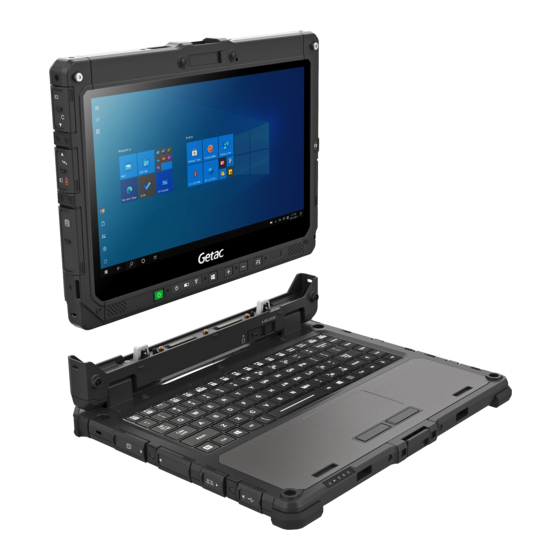
- Page 1 K120 USER MANUAL Rugged Mobile Computing Solutions...
- Page 2 All brand and product names are trademarks or registered trademarks of their respective companies. NOTE The information in this manual is subject to change without notice. For the latest version of the manual, please visit the Getac website at www.getac.com.
-
Page 3: Table Of Contents
T a b l e o f C o n t e n t s Chapter 1 Getting Started ..............Getting the Computer Running ..........2 Unpacking ................2 Installing the Battery Packs ........... 3 Installing the Micro-SIM Card (Optional) ......4 Using the Tether .............. - Page 4 Main Menu ................64 Advanced Menu ..............65 Security Menu ..............67 Boot Menu ................68 Exit Menu ................68 Chapter 6 Using Getac Software ............ OSD Control Panel ..............70 G-Manager ................71 G-Camera .................. 73 Chapter 7 Care and Maintenance ...........
- Page 5 Taking Care of the Computer ..........77 Location Guidelines ............. 77 General Guidelines .............. 77 Cleaning Guidelines ............. 78 Battery Pack Guidelines ............78 Touchscreen Guidelines ............80 When Traveling ................ 81 Chapter 8 Troubleshooting ............. Preliminary Checklist ..............83 Solving Common Problems ............
- Page 6 ENERGY STAR 7.0 ..............111 Battery Recycling ..............113...
-
Page 7: Chapter 1 Getting Started
Chapter 1 Getting Started This chapter first tells you step by step how to get the computer up and running. Then, you will find a section briefly introducing the external components of the computer. -
Page 8: Getting The Computer Running
Getting the Computer Running Unpacking After unpacking the shipping carton, you should find these standard items: z K120 Tablet z Keyboard Dock (optional) z Battery pack x 2 z AC adapter z AC power cord - or - High capacity battery... -
Page 9: Installing The Battery Packs
Installing the Battery Packs K120 has two battery compartments for two battery packs; each is installed in the same way. 1. With the battery pack correctly oriented, attach its connector side to the battery compartment at an angle ( ) and then press down the other side ( ). -
Page 10: Installing The Micro-Sim Card (Optional)
Installing the Micro-SIM Card (Optional) 1. Locate the micro-SIM card slot. Slide the protective cover to the unlocked position and open the cover. 2. Remove one screw to detach the small metal plate that covers the micro-SIM card slot. 3. Noting the orientation, insert the micro-SIM card all the way into the slot. -
Page 11: Using The Tether
Using the Tether A tether is provided for attaching the stylus to your Tablet. 1. Thread one of the tether’s loop through the hole of the stylus ( ), tie a dead knot at the end ( ), and pull the tether ( ) so that the knot fills in the hole and prevents the tether from falling off. -
Page 12: Connecting To Ac Power
Connecting to AC Power CAUTION: Use only the AC adapter included with your computer. Using other AC adapters may damage the computer. NOTE: The battery pack is shipped to you in power saving mode that protects it from charging/discharging. It will get out of the mode to be ready for use when you install the battery pack and connect AC power to the computer for the very first time. - Page 13 Tablet + Keyboard Dock: Open the cover of the power connector. Plug the DC cord of the AC adapter to the power connector ( Plug the female end of the AC power cord to the AC adapter and the male end to an electrical outlet ( 2.
-
Page 14: Turning On And Off The Computer
Turning On and Off the Computer Turning On Press the power button ( ) for at least 2 seconds until the Power Indicator lights up. The Windows operating system should start. NOTE: By default, there is 2-second delay time for the power button. You can change the setting with the “Power Button Delay”... -
Page 15: Identifying Hardware Components
Identifying Hardware Components NOTE: Depending on the model you purchased, the appearance of your computer may not be exactly the same as those shown in this manual. CAUTION: You need to open the protective covers to access the connectors. When not using a connector, make sure to close the cover completely for water- and, dust-proof integrity. - Page 16 Component Description CAUTION: When using the internal microphone, make sure the camera cover is fully closed or opened. An in-between position can interfere with the microphone function. Microphone Receives sound and voice to record voice. Camera indicator Lights up when the camera is in use. IR sensor Detects the infrared energy of objects to form an (optional)
- Page 17 Component Description Blinks green to indicate the battery’s built-in high temperature protection mechanism is activated. CAUTION: Do not remove the battery during this period. Blinks red (once per second) when the battery’s capacity is below 10%. Blinks red rapidly (once per 0.5 second) when there is a thermal protection problem.
- Page 18 Rear Components Component Description Flash Provides extra light when taking pictures. Camera lens Allows you to use the camera function. When the camera lens is in use, the indicator beside it lights up. NFC/RFID reader Reads data from NFC/RFID tags. (optional) Battery pack Supplies power to your computer when external...
- Page 19 Right-Side Components For covers with an arrowhead icon, push the cover toward one side to unlock and the other side to lock. The arrowhead points to the side for unlocking. Component Description Stylus holder Holds the stylus. Depending on the model, the component can be one of the following: None USB 2.0 port...
- Page 20 Left-Side Components For covers with an arrowhead icon, push the cover toward one side to unlock and the other side to lock. The arrowhead points to the side for unlocking. Component Description SSD canister Contains the solid-state drive, which is the mass storage device of your computer.
- Page 21 Component Description USB 3.1 Gen 1 Connects a USB device that supports USB Type-C Type-C port connection. Combo audio Connects a set of headphones or external connector speakers with amplifier. Supports a headset microphone with 4-pole TRRS 3.5mm jack. HDMI connector Connects a HDMI monitor or TV set.
-
Page 22: Keyboard Dock Components (Optional)
Component Description Docking Connect a proprietary dock such as the keyboard connectors dock, office dock, and vehicle dock. Keyboard Dock Components (Optional) NOTE: The Keyboard Dock can be purchased separately. Specific models come with the Keyboard Dock. See “Multiple Usage Modes” later in this chapter for more information. Top Components Component Description... - Page 23 Component Description Locked Unlocked Keyboard Serves as the data input device of the computer. Touchpad Serves as the pointing device of the computer. Indicators Power Lights blue when the computer is on. Blinks blue when the computer is in Sleep mode. Lights amber when the battery is being charged.
- Page 24 Right-Side Components For covers with an arrowhead icon, push the cover toward one side to unlock and the other side to lock. The arrowhead points to the side for unlocking. Component Description USB 3.0 port Connects a USB device, such as a USB flash disk, printer, digital camera, joystick, and more.
- Page 25 Component Description Kensington lock Locks the Keyboard Dock to a stationary object for security. VGA connector Connects an external display monitor. HDMI connector Connects a HDMI monitor or TV set. RJ-45 connector Connects the LAN cable. USB 3.0 port Connects a USB device, such as a USB flash disk, printer, digital camera, joystick, and more.
- Page 26 Ref Component Description Tri antenna Connects to the docking station for using external passthrough WLAN/GPS/WWAN antenna. (optional) WLAN WWAN Docking Connects a proprietary dock such as the office dock connector and vehicle dock.
-
Page 27: Multiple Usage Modes
NOTE: The Keyboard Dock can be purchased separately. Specific models come with the Keyboard Dock. With the Keyboard Dock, you can use K120 in different usage modes. (For information on how to change modes, see “Changing Usage Modes” later.) Usage Mode... -
Page 28: Changing Usage Modes
Changing usage modes means attaching or detaching the Keyboard Dock. Attaching the Keyboard Dock 1. Make sure the cover of the power connector on K120 Tablet is closed and locked. 2. Depending on the desired usage mode, have K120 Tablet face inwards or outwards. - Page 29 Detaching the Keyboard Dock 1. Push the lock of the release latch downwards to the unlocked position. 2. Slide the release latch toward the right, and while holding the latch ( lift K120 Tablet out of the holder (...
-
Page 30: Opening And Closing The Display
Opening and Closing the Display To open: 1. Pry open the cover latch ( 2. Lift up the display (i.e. K120 Tablet) ( ). You can tilt the cover forward or backward for optimal viewing clarity. CAUTION: There is a limit to the tilting angle. Do not go beyond the limit (120 degrees). - Page 31 To close: 1. Close the display. 2. Lift the cover latch to engage it on the display.
-
Page 32: Chapter 2 Operating Your Computer
Chapter 2 Operating Your Computer This chapter provides information about the use of the computer. If you are new to computers, reading this chapter will help you learn the operating basics. If you are already a computer user, you may choose to read only the parts containing information unique to your computer. -
Page 33: Navigating On The Screen
Navigating on the Screen The screen of your computer is touch-sensitive. You can operate the computer by touching the screen with your finger or the stylus. CAUTION: Do not use a sharp object such as a ballpoint pen or pencil on the touchscreen. - Page 34 The following table shows how you use the touchscreen to obtain equivalent mouse functions. Equivalent Term/Action Mouse Function Tap: Touch the screen once. Click/Point Double-tap: Touch the screen twice rapidly. Double-click Tap and hold: Tap and hold until a popup menu Right-click appears.
- Page 35 Actions Gestures Descriptions = finger down; = finger up) Rotate Use rotating to move a picture or other item on the screen in a circular direction (clockwise or counter- clockwise). The gesture Move two fingers in opposing works in applications directions.
-
Page 36: Using The Dual Mode Display (Optional)
Using the Dual Mode Display (Optional) Dual mode display (if your model has the feature) incorporates both touchscreen and digitizer functions. The display is set to Touchscreen mode by default. Touchscreen mode provides all the functionalities that an ordinary touchscreen has. When the Computer receives signals from the digitizer pen, the display automatically switches to Digitizer mode. -
Page 37: Using The Keyboard Dock
Using the Keyboard Dock NOTE: The Keyboard Dock can be purchased separately. Specific models come with the Keyboard Dock. Using the Keyboard Your keyboard has all the standard functions of a full-sized computer keyboard plus an Fn key added for specific functions. The standard functions of the keyboard can be further divided into four major categories: Typewriter keys... - Page 38 Numeric Keypad A 15-key numeric keypad is embedded in the typewriter keys as shown next: Numeric keys facilitate entering of numbers and calculations. When Num Lock is on, the numeric keys are activated; meaning you can use these keys to enter numerals.
- Page 39 Function Keys On the top row of the keys are the function keys: F1 to F12. Function keys are multi-purpose keys that perform functions defined by individual programs. Fn Key The Fn key, at the lower left corner of the keyboard, is used with another key to perform the alternative function of a key.
- Page 40 Description Switches the display output to the next choice if an external display is connected. Choices are: LCD only LCD + External display (Duplicate) LCD + External display (Extend) External display only The hot keys are equivalent to Windows logo key + P. Decreases the LCD brightness.
-
Page 41: Using The Touchpad
Using the Touchpad CAUTION: Do not use a sharp object such as a pen on the touchpad. Doing so may damage the touchpad surface. NOTE: Press Fn+F9 to toggle the touchpad on or off. For optimal performance of the touchpad, keep your fingers and the pads clean and dry. - Page 42 Term Action Point Move your finger on the pad until the cursor points to the selection on the screen. Click Press and release the left button. –or– Tap gently anywhere on the pad. Double-click Press and release the left button twice in quick succession.
-
Page 43: Using Network And Wireless Connections
Using Network and Wireless Connections Using the LAN To connect the network cable to the LAN module, connect one end of the LAN cable to the RJ-45 connector on the computer and the other end to the network hub. If you have the Keyboard Dock:... -
Page 44: Using The Wlan
Using the WLAN The WLAN (Wireless Local Area Network) module of your computer supports IEEE 802.11a/b/g/n/ac. Turning On/Off the WLAN Radio To turn on the WLAN radio: Select Æ Settings Æ Network & Internet Æ Wi-Fi. Slide the Wi-Fi switch to the On position. -
Page 45: Using The Bluetooth Feature
Using the Bluetooth Feature The Bluetooth technology allows short-range wireless communications between devices without requiring a cable connection. Data can be transmitted through walls, pockets and briefcases as long as two devices are within range. Turning On/Off the Bluetooth Radio To turn on the Bluetooth radio: Select Æ... -
Page 46: Using The Wwan Feature (Optional)
Using the WWAN Feature (Optional) A WWAN (Wireless Wide Area Network) uses mobile telecommunication cellular network technologies to transfer data. The WWAN module of your computer supports 3G and 4G LTE. NOTE: Your model only supports data transmission. Voice transmission is not supported. -
Page 47: Chapter 3 Managing Power
Chapter 3 Managing Power Your computer operates either on external AC power or on internal battery power. This chapter tells you how you can effectively manage power. To maintain optimal battery performance, it is important that you use the battery in the proper way. -
Page 48: Ac Adapter
AC Adapter CAUTION: The AC adapter is designed for use with your Computer only. Connecting the AC adapter to another device can damage the adapter. The AC power cord supplied with your Computer is for use in the country where you purchased your Computer. If you plan to go overseas with the Computer, consult your dealer for the appropriate power cord. -
Page 49: Battery Pack
Battery Pack Your computer has two battery packs. The battery pack is the internal power source for the computer. It is rechargeable using the AC adapter. NOTE: Care and maintenance information for the battery is provided in the “Battery Pack Guidelines” section in Chapter 7. Charging the Battery Pack NOTE: Charging will not start if the battery’s temperature is outside the allowed... -
Page 50: Initializing The Battery Pack
Initializing the Battery Pack You need to initialize a new battery pack before using it for the first time or when the actual operating time of a battery pack is much less than expected. Initializing is the process of fully charging, discharging, and then charging. It can take several hours. -
Page 51: Battery Low Signals And Actions
When the battery pack is not installed in the computer and you want to know the battery charge, you can press the push-button to see the number of LEDs that light up. Each LED represents 20% charge. Battery Low Signals and Actions The battery icon changes appearance to display the current state of the battery. -
Page 52: Replacing The Battery Pack
Replacing the Battery Pack CAUTION: There is danger of explosion if the battery is incorrectly replaced. Replace the battery only with the computer manufacturer’s battery packs. Discard used batteries according to the dealer’s instructions. Do not attempt to disassemble the battery pack. NOTE: You can hot swap one battery pack while the other one is supplying the power. - Page 53 4. Fit another battery pack into place. With the battery pack correctly oriented, attach its connector side to the battery compartment at an angle ( ) and then press down the other side ( ). The battery latch should automatically engage. 5.
-
Page 54: Power-Saving Tips
Power-Saving Tips Aside from enabling your computer’s power saving mode, you can do your part to maximize the battery’s operating time by following these suggestions. Do not disable Power Management. Decrease the LCD brightness to the lowest comfortable level. Shorten the length of time before Windows turn off the display. When not using a connected device, disconnect it. -
Page 55: Using Options And Peripherals
Chapter 4 Using Options and Peripherals This chapter describes the use of optional modules and the connection of peripherals. -
Page 56: Using The Fingerprint Scanner (Optional)
Using the Fingerprint Scanner (Optional) CAUTION: For optimal performance, both the scanning surface and the finger should be clean and dry. Clean the scanning surface when needed. You can use adhesive tape to remove dirt and oil from the scanner surface. It is not recommended that you use the fingerprint scanner in a below- freezing temperature. -
Page 57: Fingerprint Login
Fingerprint Login NOTE: The fingerprint login process can take a while. This is because the system has to check hardware devices and security configuration before initiating the fingerprint scanner. With an enrolled fingerprint, the user can log on by tapping the Fingerprint option in Windows login screen and then placing the finger on the scanner. -
Page 58: Using The Barcode Reader (Optional)
Using the Barcode Reader (Optional) NOTE: For enhanced applications and customization of the module, you can use the Barcode Manager program. (For detailed information on the program, see the program’s online help.) The maximum operating temperature for the barcode scanner is 50 q C (122 q F). -
Page 59: Connecting Peripheral Devices
Connecting Peripheral Devices Connecting a Display Monitor If you want the benefits of a larger display screen with higher resolution, you can connect an external display monitor to your computer The Tablet has an HDMI connector The Keyboard Dock has a VGA connector and a HDMI connector. Depending on the type of your monitor, plug the monitor’s signal connector to the HDMI or VGA connector. -
Page 60: Connecting A Usb Device
Connecting a USB Device USB Type A The Tablet has one USB 3.0 port and one USB 2.0 port (optional) for connecting USB devices, such as a digital camera, scanner, printer, modem, and mouse. USB 2.0 USB 3.0 (Select models (depending on only) your setting) -
Page 61: Connecting A Device For Usb Charging
USB 3.1 Gen 1 Type-C “USB Type-C” (or simply “USB-C”) is a physical USB connector format that features small size and free orientation. This port supports: USB 3.1 Gen 1 (up to 5 Gbps) DisplayPort over USB-C CAUTION: This port does not support USB Power Delivery. Never connect a power source to this port. -
Page 62: Connecting A Serial Device
Before connecting a device for charging, make sure the device works with the USB charging feature. Connect a device directly to this port. Do not connect via a USB hub. After resuming from sleep or hibernation, the computer may not detect the connected device. -
Page 63: Connecting An Audio Device
Connecting an Audio Device For higher audio quality, you can send sound through an external audio device. The combo connector is the “4-pole TRRS 3.5mm” type (Apple iPhone Recessed) so you can connect a compatible headset microphone. SAFETY WARNING: To prevent possible hearing damage, do not listen at high volume levels for long periods. -
Page 64: Using Various Card Readers
Using Various Card Readers Using Storage Cards The Tablet has a microSD storage card reader. The Keyboard Dock as a SDXC storage card reader. The storage card reader is a small drive for reading from and writing to removable storage cards (or called memory cards). To insert a storage card: 1. -
Page 65: Using Smart Cards (Optional)
Using Smart Cards (Optional) With an embedded microcontroller, smart cards have the unique ability to store large amounts of data, carry out their own on-card functions (e.g., encryption and mutual authentication), and interact intelligently with a smart card reader. To insert a smart card: 1. -
Page 66: Using The Nfc/Rfid Reader (Optional)
When not using an NFC/RFID card, do not leave it within or near the antenna area. For enhanced applications and customization of the module, contact your authorized Getac dealer. The NFC reader requires specialized applications. For further information, ask your system administrator. -
Page 67: Changing Or Replacing
Changing or Replacing Replacing the SSD 1. Turn off the computer and disconnect the AC adapter. 2. Locate the SSD canister and open its protective cover. 3. Pry the rubber strip ( ) to release it ( 4. Using the rubber strip, pull the SSD canister out of the slot. 5. -
Page 68: Using Bios Setup
Chapter 5 Using BIOS Setup BIOS Setup Utility is a program for configuring the BIOS (Basic Input/ Output System) settings of the computer. BIOS is a layer of software, called firmware, that translates instructions from other layers of software into instructions that the computer hardware can understand. -
Page 69: When And How To Use
When and How to Use NOTE: The actual setting items on your model may differ from those described in this chapter. The availability of some setting items depends on the configuration of your computer. You need to run BIOS Setup Utility when: You see an error message on the screen requesting you to run BIOS Setup Utility. -
Page 70: Menu Descriptions
Menu Descriptions Information Menu The Information menu contains the basic configuration information of the system. There are no user-definable items in this menu. NOTE: The “Asset Tag” information appears when you have entered the asset number for this computer using the asset management program. The program is provided in the Asset tag folder of the Driver disc. -
Page 71: Advanced Menu
Advanced Menu The Advanced menu contains the advanced settings. Wake Up Capability Any-key Wake Up From S3 state allows any key to wake up the system from S3 (Sleep) state. USB Wake-Up From S3 allows a USB device activity to wake up the system from S3 (Sleep) state. - Page 72 Virtualization Technology Setup Intel(R) Virtualization Technology enables or disables Intel® VT (Intel Virtualization Technology) feature which provides hardware support for processor virtualization. When enabled, a VMM (Virtual Machine Monitor) can utilize the additional hardware virtualization capabilities provided by this technology. Intel(R) VT for Directed I/O (VT-d) enables or disables VT-d (Intel®...
-
Page 73: Security Menu
Security Menu The Security menu contains the security settings, which safeguard your system against unauthorized use. NOTE: You can set the user password only when the supervisor password has been set. If both the supervisor and user passwords are set, you can enter any of them for starting up the system and/or entering BIOS Setup. -
Page 74: Boot Menu
Security Freeze Lock enables or disables the “Security Freeze Lock” function. This function is only applicable to SATA drives in AHCI mode. It prevents attacks on the SATA drive by freezing the security state of the drive at POST and also when the system resumes from S3. TPM Setup Menu TPM Support enables or disables TPM (Trusted Platform Module) support. -
Page 75: Using Getac Software
Chapter 6 Using Getac Software Getac software includes application programs for specific computer components and utility programs for overall management. This chapter briefly introduces the programs. -
Page 76: Osd Control Panel
OSD Control Panel The OSD (On Screen Display) Control Panel provides a user-friendly interface for you to quickly activate or operate certain functions on your computer with a simple click of the screen. To open the OSD Control Panel, start the program named OSDC. The following screen appears. -
Page 77: G-Manager
Change the function of the hardware button. Configure how your system works with the vehicle ignition. Monitor the system. View GPS information. Right-click the Getac Utility icon located on Windows taskbar and select G-Manager to start the program. The G-Manager window appears, containing several tabs. - Page 78 Help For detailed information on the program, see the program’s online help.
Need help?
Do you have a question about the K120 and is the answer not in the manual?
Questions and answers
stylist not working