Table of Contents
Advertisement
Quick Links
Advertisement
Table of Contents

Related Manuals for Hioki 2331-20


Summary of Contents for Hioki 2331-20
- Page 1 INSTRUCTION MANUAL 2331-20 POWER METER MODULE...
-
Page 3: Table Of Contents
Contents Contents Introduction ............... 1 Inspection..............1 Safety Notes ............. 2 Notes on Use ............5 Chapter 1 Overview Product Overview ........11 Major Features .......... 12 Name and Function of the Parts....19 Dimension Diagrams ......... 21 Chapter 2 Settings Setting the Module ID ........ - Page 4 Contents Chapter 4 Others Alarm Output ..........37 4.1.1 Output Rating......... 37 4.1.2 Target of Alarm Monitoring .... 38 Insulation of Internal Circuit....... 39 Chapter 5 Specifications Basic Specifications ........41 Function Specifications ......46 General Specifications ......48 Chapter 6 Maintenance and Service Cleaning ............
-
Page 5: Introduction
Introduction Introduction Thank you for purchasing the HIOKI “Model 2331- POWER METER MODULE”. obtain maximum performance from the instrument, please read this manual first, and keep it handy for future reference. Inspection When you receive the instrument, inspect it carefully to ensure that no damage occurred during shipping. -
Page 6: Safety Notes
Safety Notes Safety Notes This instrument is designed to comply with IEC 61010 Safety Standards, and has been thoroughly tested safety prior shipment. However, mishandling during use could result in injury or death, as well as damage to the instrument. Be certain that understand instructions precautions in the manual before use. - Page 7 Safety Notes The following symbols in this manual indicate the relative importance of cautions and warnings. Indicates that incorrect operation presents an extreme hazard that could result in serious injury or death to the user. Indicates that incorrect operation presents a significant hazard that could result in serious injury or death to the user.
- Page 8 Safety Notes Measurement categories (Overvoltage categories) This instrument complies with CAT III safety requirements. To ensure safe operation of measurement instruments, IEC 61010 establishes safety standards for various electrical environments, categorized as CAT I to CAT IV, and called measurement categories. These are defined as follows. CAT I Secondary electrical circuits connected to an AC electrical outlet through a transformer or similar instrument.
-
Page 9: Notes On Use
Notes on Use Notes on Use Follow these precautions to ensure safe operation and to obtain the full benefits of the various func- tions. • The maximum input voltage is as follows. U INPUT: 300 Vrms, 424.3 V peak ALARM : 30 VDC CLAMP SENSOR INPUT: 1.5 Vrms, 2.2 V peak Attempting to measure voltage in excess... - Page 10 Notes on Use Do not use the instrument near a source of strong electromagnetic radiation, or near a highly electrically charged object. These may cause a malfunction. Operation and Installation environment. Electromagnetic This instrument should be installed and operated radiation or indoors only, between 0 and 50°C (32 to 122°F) highly electrically...
- Page 11 Notes on Use When using the instrument in the case, drill ventilation holes. Drill ventilation holes or install a ventilation fan to prevent heat buildup. Wiring • When the clamp sensor is opened, do not allow the metal part of the clamp to touch any exposed metal, or to short between two lines, and do not use over bare conductors.
- Page 12 Notes on Use • Be sure to tighten the screws within the specified torque. Excessive torque may damage the terminals. Inadequate torque may result in module errors or the generation of high voltage on the CT secondary side, which may cause fire or electric shock.
- Page 13 Notes on Use • Do not connect a current sensor other than the specified clamp sensor directly to this module. Excessive input may result in module malfunc- tion. • Be careful to avoid dropping the clamps or other- wise subjecting them to mechanical shock, which could damage the mating surfaces of the core and adversely affect measurement.
- Page 14 • Before using the instrument, make sure that the insulation on the cables is undamaged and that no bare conductors are improperly exposed. Using the product in such conditions could cause an electric shock, so contact your dealer or Hioki representative for repair.
-
Page 15: Chapter 1 Overview
1.1 Product Overview Chapter 1 Overview 1.1 Product Overview • The 2331-20 is a measurement module of the Hioki "Smart Site" (remote measurement system). • This module measures and records power at regular intervals. • And the voltage, current, active power, power factor, active energy within an interval, and frequency are also can be measured. -
Page 16: Major Features
1.2 Major Features 1.2 Major Features This is a clamp-type wattmeter is used for a 100/ 200 VAC single-phase line to a 3-phase, 4-wire line. The recording interval is selectable from 1 second to 60 minutes. The maximum, minimum, and average measure- ments during the recording interval can be recorded (with sampling once a second). - Page 17 1.2 Major Features Rough Estimate of Storable Data Quantity and Time Action at memory full: Continue recording (Endless) 1P2W Recording Mode Instantaneous Instantaneous MAX/MIN/AVE Value + Value MAX/MIN/AVE Quantity of 13000 5900 4600 storable data Recording interval 1 sec. 3.5 hours 1.5 hours 1 hour 2 sec.
- Page 18 1.2 Major Features Action at memory full: Continue recording (Endless) 1P3W/3P3W Recording Mode Instantaneous Instantaneous MAX/MIN/AVE Value + Value MAX/MIN/AVE Quantity of 10000 4400 3400 storable data Recording interval 1 sec. 2.5 hours 1 hour 0.5 hours 2 sec. 5.5 hours 2 hours 1.5 hours 5 sec.
- Page 19 1.2 Major Features Action at memory full: Continue recording (Endless) 3P4W Recording Mode Instantaneous Instantaneous MAX/MIN/AVE Value + Value MAX/MIN/AVE Quantity of 8800 3500 2700 storable data Recording interval 1 sec. 2 hours 0.5 hours 0.5 hours 2 sec. 4.5 hours 1.5 hours 1.5 hours 5 sec.
- Page 20 1.2 Major Features Action at memory full: Stop recording (Memory full stop) 1P2W Recording Mode Instantaneous Instantaneous MAX/MIN/AVE Value + Value MAX/MIN/AVE Quantity of 15000 6800 5300 storable data Recording interval 1 sec. 4 hours 1.5 hours 1 hour 2 sec. 8.5 hours 3.5 hours 1.5 hours...
- Page 21 1.2 Major Features Action at memory full: Stop recording (Memory full stop) 1P3W/3P3W Recording Mode Instantaneous Instantaneous MAX/MIN/AVE Value + Value MAX/MIN/AVE Quantity of 12000 5100 3900 storable data Recording interval 1 sec. 3 hours 1 hour 1 hour 2 sec. 6.5 hours 2.5 hours 2 hours...
- Page 22 1.2 Major Features Action at memory full: Stop recording (Memory full stop) 3P4W Recording Mode Instantaneous Instantaneous MAX/MIN/AVE Value + Value MAX/MIN/AVE Quantity of 10000 4000 3100 storable data Recording interval 1 sec. 2.5 hours 1 hour 0.5 hours 2 sec. 5.5 hours 2 hours 1.5 hours...
-
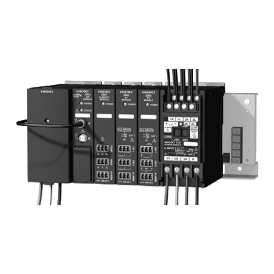
Page 23: Name And Function Of The Parts
1.3 Name and Function of the Parts 1.3 Name and Function of the Parts Front CLAMP SENSOR ALARM terminals INPUT terminals U RANGE POWER LED switch Mark area U INPUT terminals Back Module ID setting dial... - Page 24 VAC) or 200 V (140 to 260 VAC). Module ID setting Use the dial to set the module's identifica- tion No. dial *1: The module needs repair. Contact your vendor (agent) or nearest Hioki office. *2: The same module ID may be used by another module.
-
Page 25: Dimension Diagrams
1.4 Dimension Diagrams 1.4 Dimension Diagrams ± ± ± 103.9 (Unit: mm) - Page 26 1.4 Dimension Diagrams...
-
Page 27: Chapter 2 Settings
2.1 Setting the Module ID Chapter 2 Settings 2.1 Setting the Module ID You can connect up to 63 measurement modules to one communications module. Setting Procedure Use the module ID setting dial to set the ID No. of the module to a number from 01 and to 63. (You cannot set a number other than the above.) •... - Page 28 2.1 Setting the Module ID...
-
Page 29: Chapter 3 Preparations
3.1 Installing the Module Chapter 3 Preparations 3.1 Installing the Module 3.1.1 Installing the Module Base Do not mount the module base on the ceiling where it may fall off. Fasten the module base to a DIN rail or the wall according to the procedure described in the 2391 or 2392 series MODULE BASE instruction man- ual. -
Page 30: Connecting The Clamp Sensor To Module
3.2 Connecting the Clamp Sensor to Module 3.2 Connecting the Clamp Sensor to Module Remove the cover from the module. Connect the clamp sensor cables to the module's CLAMP SENSOR INPUT terminals (at a tightening torque of 0.5 N•m). ❖ "Connection diagram"... - Page 31 3.2 Connecting the Clamp Sensor to Module Terminals M3.0 screws are used for the terminal blocks for this module and the clamp sensors. For connec- tion, a round crimp connector (RAV 1.25-3) is rec- ommended. Cables The 9695-02 and 9695-03 use terminal blocks. Therefore, various types of cables may be usable.
-
Page 32: Connecting The Voltage Cable To The Module
3.3 Connecting the Voltage Cable to the Module 3.3 Connecting the Voltage Cable to the Module Use the U RANGE switch to select 100 V (70 to 130 VAC) or 200 V (140 to 260 VAC). Connect voltage cables to the U INPUT terminals (at a tightening torque of 0.8 N•m). -
Page 33: Connecting Alarm Output
3.4 Connecting Alarm Output 3.4 Connecting Alarm Output Design the wiring to prevent short-circuiting of the ALARM and CLAMP SENSOR INPUT terminals, thus avoiding electric shock and accidents due to short-circuiting. The terminal blocks use M3.0 screws (at a tighten- ing torque of 0.5 N•m). -
Page 34: Connecting To The Measured Line
3.5 Connecting to the Measured Line 3.5 Connecting to the Measured Line • U INPUT terminals 1 to 3 share the N terminal; inputs to these terminals are not insulated from each other. Be careful to avoid electric shock and short-circuiting. •... - Page 35 3.5 Connecting to the Measured Line In order to prevent electric shock and short- circuit accidents, shut off the power to the line to be measured before connecting the clamp sensors and voltage cords. • Avoid stepping on or pinching cables, which could damage the cable insulation.
- Page 36 3.5 Connecting to the Measured Line • Ensure that the measured line is correctly set and connection correctly made to ensure accurate measurement. • Clamp the cladding of the wire by placing the clamp with the arrow on it facing the load side. •...
- Page 37 3.5 Connecting to the Measured Line Connection diagram Measurement of single-phase, 2-wire line Power supply side 1K 1L 2K 2L - 3K 3L ALARM U1 U2 U3 N...
- Page 38 3.5 Connecting to the Measured Line Connection diagram Measurement of singe-phase, 3-wire line or 3-phase, 3-wire line Power supply side 1K 1L 2K 2L - 3K 3L ALARM U1 U2 U3 N Load side...
- Page 39 3.5 Connecting to the Measured Line Connection diagram Measurement of singe-phase, 3-wire line or 3-phase, 3-wire line using CT and VT (PT) Power supply side Current trans- former Current trans- former 1K 1L 2K 2L - 3K 3L ALARM Voltage transformer VT (PT) U1 U2 U3 N...
- Page 40 3.5 Connecting to the Measured Line Connection diagram Measurement of 3-phase, 4-wire line Power supply side 1K 1L 2K 2L - 3K 3L ALARM U1 U2 U3 N N Load side INPUT: 3PHASE 4WIRE...
-
Page 41: Chapter 4 Others
4.1 Alarm Output Chapter 4 Others 4.1 Alarm Output 4.1.1 Output Rating Ensure that the input does not exceed the maximum input voltage or current to avoid module damage, short-circuiting and electric shock resulting from heat building. Output method Open collector Maximum input 30 V, 20 mA max. -
Page 42: Target Of Alarm Monitoring
4.1 Alarm Output Circuit diagram Power Power Relay Limit resistor Diode Output ALARM+ Output ALARM+ ALARM- ALARM- Connecting LED Connecting relay • When connecting a relay or LED lamp, ensure that the relay or lamp operates at up to 30 V and 20 mA (with allowable loss of 75 mW or less). -
Page 43: Insulation Of Internal Circuit
INPUT terminals. Beware of electric shock and short- circuiting. Moreover, be sure to cover the measured line when live. In the 2331-20, the input circuit and alarm output are insulated from the CAN bus as shown in the block diagram below. (Withstand voltage: 2.21... - Page 44 4.2 Insulation of Internal Circuit...
-
Page 45: Chapter 5 Specifications
5.1 Basic Specifications Chapter 5 Specifications 5.1 Basic Specifications Condition of guaranteed accuracy Condition of 10-minute warming-up time, Sine wave Guaranteed input, Power factor =1, Maximum rated accuracy voltage to earth=0 V Period of Guaranteed One year Accuracy Effective Voltage : 70%f.s. to 130%f.s. Measurement Current : 2%f.s. - Page 46 (Depends on the clamp sensor used.) Measurement Voltage : ±1.0%f.s. Accuracy Current : ±1.0%f.s. + Clamp sensor accuracy Current range 2331-20 Current Range Clamp Sensor and Its (Selectable using the PC Current Range application) 1 A (100 mV/A) 9765 5 A (20 mV/A)
- Page 47 5.1 Basic Specifications Power range Current Voltage 1.000 A 5.000 A 50.00 A 100.0 A 200.0 A 500.0 A 1.000 kA /Wiring 100.0 500.0 5.000 10.00 20.00 50.00 100.0 1P2W 1P3W 200.0 1.000 10.00 20.00 40.00 100.0 200.0 100.0 V 3P3W 300.0 1.500...
- Page 48 5.1 Basic Specifications Power Factor Measurement Power factor PF 0 to 1 Range Measurement ±5%rdg. Accuracy (At full-scale input with power factor of 1) Frequency measurement Measurement Frequency FREQ 40Hz to 70Hz Range ±0.5%rdg. Measurement (When input is 70% to 130% f.s. of voltage Accuracy range) Object to be...
- Page 49 5.1 Basic Specifications Voltage : Less than 0.5% f.s. of measurement Current : Less than 0.5% f.s. of Zero Suppression measurement (less than 0.9% f.s. when using the 9695-02 with 5A range selected) Power : When voltage or current is 0...
-
Page 50: Function Specifications
5.2 Function Specifications 5.2 Function Specifications One data set contains time, voltage, current, effective power, power factor, Active energy within an interval, frequency • Instantaneous recording mode 1P2W U1, I1, P, PF, Wh+, FREQ 1P3W/3P3W U1, U2, I1, I2, P, PF, Wh+, FREQ 3P4W U1, U2, U3, I1, I2, I3, P, PF,... - Page 51 All items of data are deleted by a command. Data Deletion New data will be added to the previous data at the start of recording. After recovering from a power outage, the Power Outage 2331-20 automatically returns to the state Protection held before the outage.
-
Page 52: General Specifications
5.3 General Specifications 5.3 General Specifications U INPUT: Insulated input (Not insulated from current measurement Input Method circuit) CLAMP SENSOR INPUT: Input insulated by a clamp sensor Input Resistance U INPUT: 1.6 MΩ ± 10% (Difference input) (50/60 Hz) CLAMP SENSOR INPUT: 200 kΩ ± 10% Measurement Digital sampling Method... - Page 53 5.3 General Specifications 3.536 kVAC Between U INPUT terminals and Case (excluding terminal section) 2.210 kVAC Between U INPUT terminals and ALARM terminals, Withstanding interface terminals Voltage CLAMP SENSOR INPUT terminals and ALARM terminals, Interface terminals (50/60 Hz, Response current 5 mA, one minutes Approx.
- Page 54 5.3 General Specifications...
-
Page 55: Cleaning
Be sure to include details problem. Hioki cannot responsible for damage that occurs during shipment. • When transporting the 2331-20 or a system containing this module, tape the front of the module or take similar measures to avoid losing internal components. - Page 56 6.2 Service...
- Page 59 HIOKI 2331-20 POWER METER MODULE Instruction Manual Publication date: August 2004 Edition 1 Edited and published by HIOKI E.E. CORPORATION Technical Support Section All inquiries to International Sales and Marketing De- partment 81 Koizumi, Ueda, Nagano, 386-1192, Japan TEL: +81-268-28-0562 / FAX: +81-268-28-0568 E-mail: os-com@hioki.co.jp...
- Page 60 HEAD OFFICE 81 Koizumi, Ueda, Nagano 386-1192, Japan TEL +81-268-28-0562 / FAX +81-268-28-0568 E-mail: os-com@hioki.co.jp URL http://www.hioki.co.jp/ HIOKI USA CORPORATION 6 Corporate Drive, Cranbury, NJ 08512, USA TEL +1-609-409-9109 / FAX +1-609-409-9108 2331A981-00 04-08H Printed on recycled paper...
Need help?
Do you have a question about the 2331-20 and is the answer not in the manual?
Questions and answers