Advertisement
Quick Links
...................................................................................................................
1
Introduction
..........................................................................................................................
2
3
4
Schematic and Bill of Materials
.................................................................................................................................
1
2
3
4
5
1
EVM Preset Output Voltage
2
Maximum Load Current
3
Factory EVM Jumper Settings
4
1
Introduction
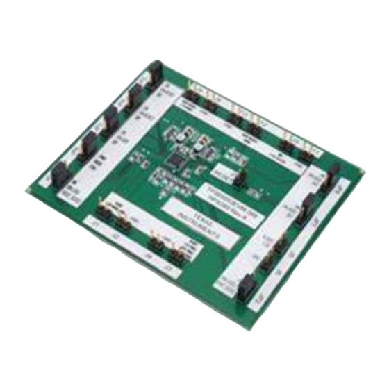
The Texas Instruments TPS65053EVM-389 evaluation module (EVM) enables designers to evaluate the
operation and performance of the TPS65053 Power Management Integrate Circuit (PMIC) for applications
that require multiple power rails and are powered from a single Lithium Ion or Lithium Polymer cell. The
TPS65053 contains two efficient step-down switching converters, three low dropout (LDO) linear
regulators and a voltage monitor RESET output.
The TPS65053EVM-389 is setup according to the power requirements of the Freescale™ i.MX27
processor.
SLVU262 - February 2009
Submit Documentation Feedback
.................................................................................................................
............................................................................................
..............................................................................................................
...........................................................................................................
.......................................................................................................
............................................................................................
................................................................................................
.....................................................................................................
.............................................................................................
.....................................................................................
TPS65053EVM-389
Contents
List of Figures
List of Tables
User's Guide
SLVU262 - February 2009
1
2
6
8
5
6
7
8
9
4
4
5
10
TPS65053EVM-389
1
Advertisement

Related Manuals for Texas Instruments TPS65053EVM-389


Summary of Contents for Texas Instruments TPS65053EVM-389
-
Page 1: Table Of Contents
Lithium Ion or Lithium Polymer cell. The TPS65053 contains two efficient step-down switching converters, three low dropout (LDO) linear regulators and a voltage monitor RESET output. The TPS65053EVM-389 is setup according to the power requirements of the Freescale™ i.MX27 processor. SLVU262 – February 2009... -
Page 2: Setup
Setup This chapter describes the jumpers and connectors on the EVM, as well as how to properly connect, setup, and use the TPS65053EVM-389. Input/Output Connector Descriptions J1 - VLDO1 This header is the positive output of LDO1 linear regulator. This output is externally adjustable for the TPS65053 and is programmed to a value of 1.8 V on the EVM. - Page 3 Placing a shorting bar between EN LDO3 and ON ties the EN pin of LDO3 to VIN, thereby enabling LDO3. Placing a shorting bar between EN LDO3 and OFF ties the EN pin of LDO3 to GND, thereby disabling LDO3. SLVU262 – February 2009 TPS65053EVM-389 Submit Documentation Feedback...
- Page 4 VLD03 200 mA Power Up Sequence The TPS65053EVM-389 is set up to meet the Power Up requirements of the Freescale™ i.MX27 processor. The step down converters DCDC1 and DCDC2 start up first, followed by the low drop out (LDO) regulators LDO1, LDO2 and LDO3 as shown in...
- Page 5 Between VOUT_DCDC1 and VIN_LDO1 Between VOUT_DCDC1 and VIN_LDO2 Between ON and EN_LDO1 Between ON and EN_DCDC2 Between ON and EN_DCDC1 Between PWM and MODE Between ON and EN_LDO2 Between ON and EN_LDO3 SLVU262 – February 2009 TPS65053EVM-389 Submit Documentation Feedback...
-
Page 6: Board Layout
Board Layout www.ti.com Board Layout This chapter provides the TPS65053EVM-389 board layout and illustrations. Layout Figure 2 Figure 3 show the board layout for the TPS65053EVM-389 PWB. Figure 2. Assembly Layer TPS65053EVM-389 SLVU262 – February 2009 Submit Documentation Feedback... -
Page 7: Top Layer Routing
Board Layout www.ti.com Figure 3. Top Layer Routing SLVU262 – February 2009 TPS65053EVM-389 Submit Documentation Feedback... -
Page 8: Bottom Layer Routing
Schematic and Bill of Materials www.ti.com Figure 4. Bottom Layer Routing Schematic and Bill of Materials This chapter provides the TPS65053EVM-389 schematic and bill of materials. TPS65053EVM-389 SLVU262 – February 2009 Submit Documentation Feedback... - Page 9 Schematic and Bill of Materials www.ti.com Schematic Figure 5. TPS65053EVM-389 Schematic SLVU262 – February 2009 TPS65053EVM-389 Submit Documentation Feedback...
-
Page 10: Tps65053Evm-389 Bill Of Materials
Related Documentation From Texas Instruments www.ti.com Bill of Materials Table 4. TPS65053EVM-389 Bill of Materials Count RefDes Value Description Size Part Number C1, C2, C3, C4, C5, Capacitor, Ceramic, 10V, X5R, 10uF 0805 GRM21BR61A106KE19L muRata C11, C14 33pF Capacitor, Ceramic, 50V, C0G, 5%... - Page 11 EVALUATION BOARD/KIT IMPORTANT NOTICE Texas Instruments (TI) provides the enclosed product(s) under the following conditions: This evaluation board/kit is intended for use for ENGINEERING DEVELOPMENT, DEMONSTRATION, OR EVALUATION PURPOSES ONLY and is not considered by TI to be a finished end-product fit for general consumer use. Persons handling the product(s) must have electronics training and observe good engineering practice standards.
- Page 12 IMPORTANT NOTICE Texas Instruments Incorporated and its subsidiaries (TI) reserve the right to make corrections, modifications, enhancements, improvements, and other changes to its products and services at any time and to discontinue any product or service without notice. Customers should obtain the latest relevant information before placing orders and should verify that such information is current and complete.
Need help?
Do you have a question about the TPS65053EVM-389 and is the answer not in the manual?
Questions and answers